

Za prijevod dokumentacije odaberite jezik koji vas zanima u nastavku.
Structural section of the construction and building design
For the repetitive architectural and construction project of a single-family residential building DM-6804
The study includes:
I. Technical description:
- Basis of the study.
- Subject of the study.
- Location and geotechnical (soil and water) conditions.
- Materials.
- Technical description of the structure.
- Anti-corrosion protection.
- Final remarks.
- Standards and literature.
II. Load Summary
III. Structural and Strength Calculations including structural description
IV. Drawings:
- Layout of structural elements – foundations
- Layout of structural elements – ground floor
- Layout of structural elements – floor slab over the ground floor
- Layout of structural elements – attic
- Layout of structural elements – roof
- Characteristic sections
- Reinforcement of reinforced concrete elements
- Reinforcement of reinforced concrete elements
- Reinforcement of reinforced concrete elements
- Reinforcement of reinforced concrete elements
- Reinforcement of reinforced concrete elements
- Reinforcement of reinforced concrete elements
- Reinforcement of reinforced concrete elements
I. Technical description
1. Basis of the study
The study is based on:
- the investor's commission
- a standard building design by KB Projekt Kraków
- industry standards and professional literature
2. Subject of the study
The subject of this study is the structural design of a standard single-family residential building. The scope of the study complies with the conditions specified in the Regulation of the Minister of Infrastructure of July 3, 2003, regarding the detailed scope and form of a construction project. The project has been prepared for general geotechnical (soil and water) conditions, snow loads, and wind loads.
3. Location and geotechnical conditions
The building is located in snow load zone 3 and wind load zone 1. Medium silts (Mi) with a liquidity index IL=0.25 were assumed at the foundation level, which corresponds to a bearing capacity of approximately 320 MPa. The project is adapted to the following zone conditions:
- Snow zone 3 according to PN-EN 1991:1:3
- Wind zone 1 according to PN-EN 1991-1-4
- The frost penetration depth was assumed to be at least −1.0 m below the adjacent ground level. The adopted foundation level is −1.2 m below ground level.
Simple geotechnical conditions and the absence of groundwater were assumed at the foundation level.
The geotechnical category of the facility depends on the complexity of the structure, foundations, impacts, and geotechnical conditions. As a building with a simple structure, supported on direct foundations, it is proposed to be classified as Geotechnical Category I, based on the regulation of the MTBiGM of April 25, 2012.
4. Materials
- Foundation concrete: B25 (C25/30) W8
- Concrete for beams and columns: B25 (C20/25)
- Lean concrete (blinding layer): B15 (C12/15)
- Reinforcing steel: A-IIIN BSt500S
- Structural timber (load-bearing): C24 grade, maximum moisture content 18%
- Bolts: Class 8.8, hot-dip galvanized
- Steel: S235JR, hot-dip galvanized
- Carpentry connectors: Galvanized
- Structural walls:
- Load-bearing walls (ground floor and first floor): Ceramic blocks, class 15 MPa
- Mortar for walls above ground level: Cement-lime mortar
5. Technical description of the structure
The designed facility is a single-family house without a basement and with a usable attic. The total external dimensions of the building at the face of the load-bearing walls are 15.10 x 13.90 m (measured along the outer perimeter of the load-bearing walls), while the ridge height is approx. 8.08 m above the ±0.00 level. The building should be constructed using traditional technology as a masonry structure supported on direct foundations in the form of footings and pads, with a reinforced concrete floor slab over the ground floor, a wooden roof truss, and a roof over the veranda and entrance.
5.1 Roof structure
The roof structure over the main building is designed as a rafter-and-collar beam truss, the main elements of which are 8.5 x 20 cm rafters with a maximum axial spacing of 90 cm, supported on 16 x 16 cm wall plates. Between the rafters, 2 x 8 x 20 cm collars with two spacers every 1.83 m are to be installed. Wall plates should be anchored to the ring beam with ø16 anchors every 1.5 m. At the roof peak, a stiffening ridge purlin has been designed, and at the junction of rafters and collars, longitudinal 16 x 16 cm stiffening purlins.
The maximum weight of the roof covering including battens must not exceed 20 kg/m².
5.2 Roof structure over the veranda and entrance
Dormers over the entrance and veranda are designed as a rafter-and-collar beam truss with 8 x 20 cm rafters at a maximum spacing of 90 cm, with 8 x 20 cm collars and longitudinal stiffening by a 16 x 16 cm ridge purlin. The ridge purlin should be supported on the load-bearing walls of the dormer and connected with valley purlins, which in turn connect with the longitudinal purlins of the building – the whole structure is to form a rigid assembly transferring the weight from the sections of the broken roof planes.
5.3 Load-bearing masonry walls
Load-bearing walls of the above-ground floors are to be made of 15 MPa ceramic blocks with a wall thickness of 25 cm, using cement-lime mortar. In areas of stress concentration and at the support points of the roof support structure, reinforced concrete strengthening columns made of C20/25 concrete reinforced with A-IIIN (BSt500S) steel have been designed, with cross-sections and reinforcement intensity according to the respective structural item.
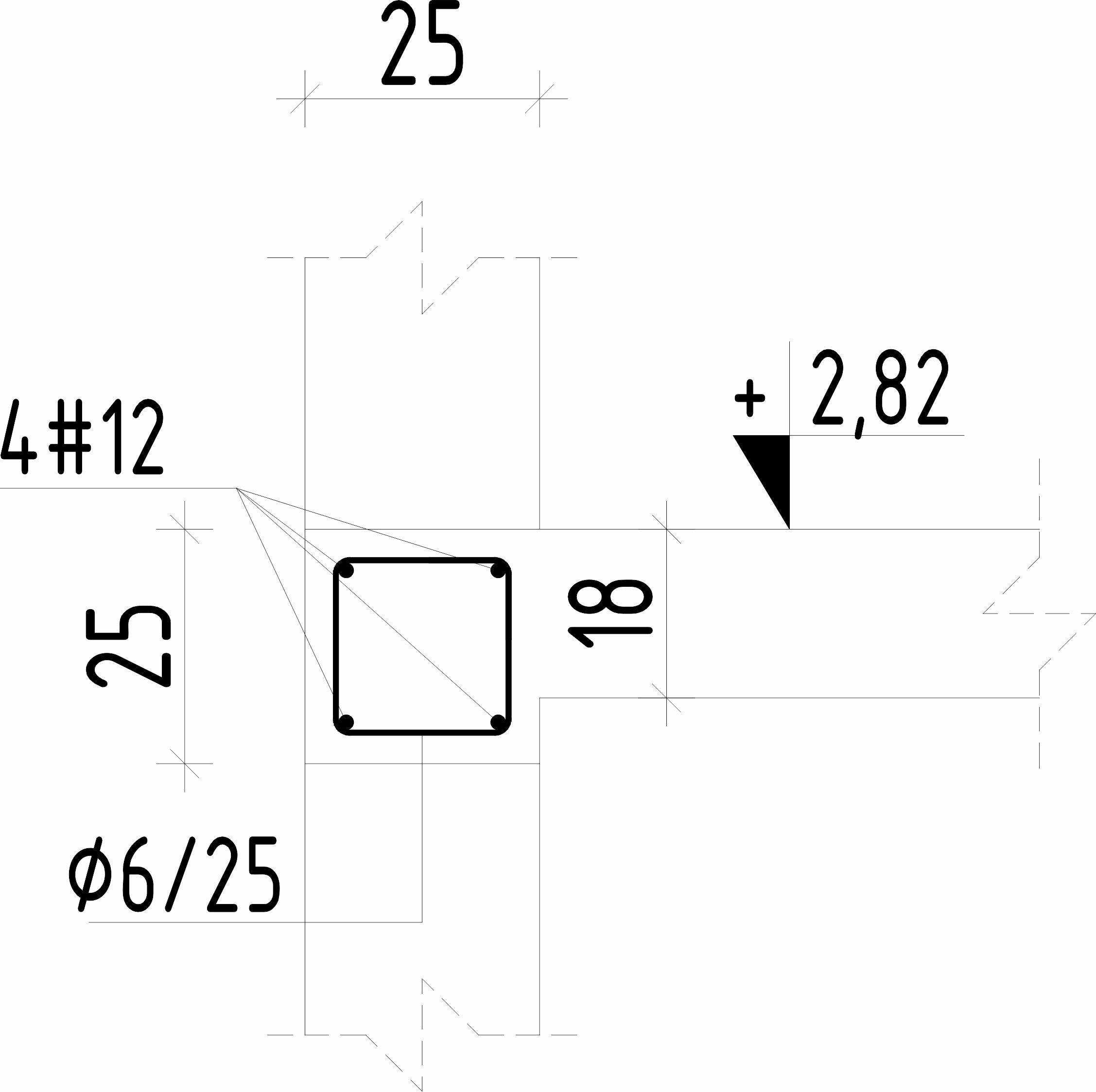
The ring beams of the attic walls (knee walls and gable walls) 25 x 25 cm are to be made of reinforced concrete, using C20/25 concrete and A-IIIN (BSt500S) steel – reinforced longitudinally with 2x3#12 bars and Φ6 stirrups every 25 cm (the stirrup spacing should be reduced by half at the longitudinal bar lap locations).
Ring beams at the ground floor slab level 25 x 25 cm are to be made of reinforced concrete, using C20/25 concrete and A-IIIN (BSt500S) steel – reinforced longitudinally with 2x2#12 bars and Φ6 stirrups every 25 cm (the stirrup spacing should be reduced by half at the longitudinal bar lap locations).
Lintels in the load-bearing masonry walls should be made as cast-in-place reinforced concrete using C20/25 concrete reinforced with A-IIIN (BSt500S) steel. Cross-sections and reinforcement intensity according to the respective structural item. In support zones, i.e., over a section of 1/6 of the lintel span measured from the face of the opening, the stirrup spacing should be reduced by half.
Foundation walls are to be made as monolithic reinforced concrete, 25 cm thick, using C20/25 W8 concrete, reinforced vertically on both sides with #12 bars every 15 cm and horizontally with #10 bars every 20 cm.
5.4 Partition walls
Ground floor partition walls are designed as masonry made of 12 cm thick ceramic blocks using cement-lime mortar. Lintels in partition walls should be made using typical system "L" or "U" fittings; however, for opening spans not exceeding 90 cm, it is also permitted to make them as masonry reinforced with 3Ø8 bars.
Attic partition walls are to be made of class 400 aerated concrete blocks using cement-lime mortar. Lintels in these partition walls should be made using typical system "L" or "U" fittings; however, for opening spans not exceeding 90 cm, it is also permitted to make them as masonry reinforced with 3Ø8 bars.
5.5 Floor slabs
The floor slab over the ground floor is designed as a monolithic reinforced concrete slab, 18 cm thick, made of C20/25 concrete, cross-reinforced with BST500S steel bars (#12 and #10) according to the layout in the structural drawing. The concrete cover for the reinforcement of reinforced concrete slabs is 20 mm.
5.6 Reinforced concrete beams and columns
The wall-bearing structural system of the building is supplemented by reinforced concrete columns and beams located both inside and outside the designed facility. These should be constructed as monolithic elements cast in situ using C20/25 grade concrete and reinforced longitudinally with AIIIN (BSt500S) steel bars and stirrups – in accordance with the guidelines provided in the calculation section. The minimum bearing length of reinforced concrete beams on the masonry is 25 cm.
For all columns and beams in the above-ground part, exposure class XC3 and a 30 mm cover were adopted.
5.7 Foundation slab (slab on grade)
The slab on grade is to be made of c25/30 concrete, 10 cm thick, placed on 15 cm of lean concrete. It is essential to ensure the removal of the humus layer and non-load-bearing soils. The slab should be structurally reinforced with a mesh of #8 mm (BSt500S) bars with a mesh size not exceeding 15 cm. Finishing layers in the slab should be executed according to the specifications provided in the architectural design.
The ground surface directly adjacent to the building walls should be leveled with a slope away from the building, and a sealed concrete apron should be laid around the building to prevent rainwater infiltration. To ensure proper drainage of the area around the building, a drainage system should be installed, using non-cohesive soil that does not retain rainwater for backfilling. Before laying the foundations, the site manager and an authorized geotechnical engineer must inspect and approve the soil and water conditions, confirmed by an entry in the building log – both before and after the soil replacement.
5.7 Staircase - internal stairs
In the designed facility, the vertical communication route connecting the ground floor with the attic consists of reinforced concrete plate stairs, 18 cm thick, reinforced according to the structural scheme in the detailed drawing. The concrete cover for the stair reinforcement is 20 mm.
6. Anti-corrosion protection
Wooden elements of the building structure must be protected against biological corrosion and pests by applying two coats of "intox s" salt preparation according to the manufacturer's guidelines or other agents approved for use in residential construction.
7. Implementation recommendations
- For foundations, use ordinary C20/25 concrete reinforced with AIIIN – BSt500S steel (as indicated in the calculation section), meeting standard conditions regarding composition, samples, properties, and the cement used.
- For the above-ground reinforced concrete structure, use ordinary C20/25 concrete reinforced with AIIIN – BSt500S steel (as indicated in the calculation section), meeting standard conditions regarding composition, samples, properties, and the cement used.
- The use of concrete admixtures depends on the contractor and is a result of the developed construction technology, prevailing temperature, and the pace of construction work.
- Minimum concrete cover for reinforcing steel in reinforced concrete elements (unless stated otherwise for specific structural items in the calculation section) for anti-corrosion reasons (exposure class XC4 – foundations, foundation walls; XC3 – others):
- Foundations: 5.0 cm
- Reinforced concrete slabs and stairs: 2.0 cm
- Reinforced concrete columns and beams: 3.0 cm
- After pouring, the concrete must be cured, e.g., by covering with foil and sprinkling with water. In the case of very high or low temperatures, concrete surfaces should be shielded, e.g., with straw mats. The curing period depends on the prevailing temperatures but should not be shorter than 7 days. Foundation walls should remain in the formwork for at least three days. Early removal of formwork may lead to shrinkage cracks.
- Periods between the casting of an element and its striking (formwork removal) and loading must be strictly observed, because:
- Early stripping of foundation wall formwork causes rapid drying, which often leads to vertical, through-thickness shrinkage cracks; these cracks may span the entire height of the element or occur only in its lower part.
- Removing formwork after a few days and replacing it with individual point supports changes the structural scheme of the element and may cause excessive stress in the not-yet-fully bonded concrete, resulting in micro-damage to its internal structure; this can lead to excessive deflections. This phenomenon is exacerbated by the very high creep coefficient characteristic of young concrete.
- It is unacceptable to apply additional loads to concrete structural elements before 28 days have passed from the time of casting. Deformations of structural elements due to the young age of the concrete and micro-damage to its structure may be greater than those resulting from calculations.
- Carrying out finishing works immediately after the completion of the shell stage or during the construction of the facility usually leads to damage to finishing elements; in the initial “life” of the structure, significant deformations of individual building elements occur due to:
- increased vertical loads during the construction of the building,
- rheological processes,
- evaporation and binding of moisture contained in reinforced concrete elements,
- the so-called “adjustment” of structural elements to the loads applied to them.
- The type, thickness, and arrangement of insulation layers and finishing elements shall be according to the architectural specification.
- Leveling screeds and floors should be reinforced with a mesh of Ø4.5 mm bars at 15/15 cm spacing.
- Under the reinforced screed of the above-ground floors, use an insulation layer of hard expanded polystyrene (EPS), extruded polystyrene (XPS), or others with similar properties.
- Non-load-bearing walls – partition and cladding walls – should be constructed in such a way that they are not loaded by beams and floor slabs; the use of soft EPS (FS10) spacers with a thickness of 2 cm or dry construction systems, e.g., gypsum-plasterboard on a frame, is recommended. Partition and cladding walls should be built after the reinforced concrete structure has been completed and the formwork removed.
- Earthworks should be carried out with particular care; excavations should not be made without prior protection of the walls of neighboring buildings. Furthermore, the loosening of the native soil within the slab area must not be allowed – the last layer of native soil should be removed immediately before pouring the lean concrete layer.
8. Final remarks
8.1 General remarks
Prior to the commencement of works, a detailed execution design must be prepared for the reinforced concrete elements included in the investment.
Before starting works, the site management and the Supervision Inspector should thoroughly familiarize themselves with the entire technical documentation, paying attention to its coordination with other industry designs. Any comments must be presented to the Designer before the start of works.
Building materials used must have the required certificates and comply with the conditions resulting from Polish Standards. Materials in contact with food must have a PZH (National Institute of Hygiene) certificate. Any material or structural changes relative to the design must be agreed upon with the Investor and the Designer as part of the author's supervision agreement.
Use element cross-sections according to the design and appropriate connections for wooden elements. All reinforced concrete elements must be made of concrete of the grade specified in the study.
8.2 General Occupational Health and Safety (OHS) remarks during construction
All works must be carried out in accordance with Polish Standards, Technical Regulations, OHS Regulations, and the Building Craft.
Before starting work, every employee must be trained in the regulations applicable on the construction site. During the performance of works, the regulations contained in the Regulation of the Ministry of Infrastructure of February 6, 2003, on occupational health and safety during the performance of construction works (Journal of Laws No. 47, item 401) must be observed.
The applicable general OHS conditions should be supplemented, if necessary, by the site management with additional requirements resulting from the specifics and local conditions of the works. In terms of fire protection, the contractor performing assembly works on the construction site is obliged to comply with normative acts. Any potential welding work should be performed by qualified welders.
8.3 Foundations
Earthworks should be carried out in the dry season and in positive temperatures, preventing excessive moisture and freezing of the excavation. The last 20 cm of the excavation depth should be removed with light equipment immediately before the base layers are installed. Under no circumstances may the facility be founded on a layer of disturbed soil. In the event of non-load-bearing soil pockets in the bottom of the excavation (e.g., quicksand, peat, humus, etc.) or other unfavorable geological phenomena, the soil must be replaced – filling with lean concrete is recommended – and a qualified geotechnician performing the soil inspections and the Designer must be notified. They, in consultation with the Contractor and Investor representatives, will agree on the method of soil reinforcement. In the immediate vicinity of existing buildings, the base layers should be compacted using static methods (e.g., static rollers).
8.4 Concrete and reinforced concrete elements
During concreting, the concrete must be compacted and then cured during the setting period in accordance with the "Technical Conditions for the Execution and Acceptance of Construction and Assembly Works." For reinforcement, use steel without an iron oxide coating that reduces the bond between steel and concrete (only slight surface patination of the steel is allowed). The concrete cover for reinforcing steel in reinforced concrete elements (for anti-corrosion and fire protection reasons) – according to point 8, letter d.
8.5 Masonry walls
In accordance with technical conditions and guidelines, wall pillars with a cross-sectional area of less than 0.09 m² are not allowed. Pillars with an area of 0.09 m² < As < 0.20 m² should be built of solid blocks, if possible without vertical joints that reduce the load-bearing capacity of the pillar. Any wall elements with a cross-sectional area As < 0.09 m² should be made of reinforced concrete or be non-load-bearing.
Mutually perpendicular or diagonal walls should be connected to each other by bonding or metal connectors. It is recommended that mutually perpendicular or diagonal structural walls be erected simultaneously. Use products no smaller than half-units and ensure the bonding of masonry units in accordance with standard recommendations (masonry units should overlap by a length equal to at least 0.4 of the layer height or 40 mm).
Masonry works are allowed in category B, i.e., under the supervision of a qualified foreman. Maximum execution deviations of the wall should not exceed:
- vertically: 20 mm over the height of a story or 50 mm over the height of the building
- horizontal displacement: 20 mm in the wall axes above and below the floor slab
- deviation from a straight line (bulging): 5 mm and no more than 20 mm over 10 m
Joint thickness is allowed within the range of 8 mm–15 mm (does not apply to thin-joint masonry).
During masonry work:
- observe proper bonding, maintaining the principle of staggering vertical joints in subsequent wall layers by a minimum of 6 cm
- cut blocks and ceramic elements to the desired size with a ceramic/concrete saw (breaking elements with a hammer or in any other impact way is not allowed)
- lay the mortar evenly in a layer 8–10 mm thick
- before applying the mortar, moisten the surface of the masonry units abundantly with water to avoid drawing water out of the mortar
- execute longitudinal and transverse walls simultaneously, bonding them appropriately
- protect the completed part of the wall against precipitation with a foil cover
- when erecting walls from "tongue and groove" elements, special attention should be paid to their tight fit
- when installing utilities, perform chases and openings using specialized tools
- observe the principle of "not undercutting" the wall with a horizontal chase
The adopted materials and dimensions of the facility allow for the realization of masonry walls without the use of thermal expansion joints. Horizontal and diagonal chases should be avoided in masonry walls.
8.6 Anti-corrosion protection
The elements of the reinforced concrete structure are classified into the following exposure classes: foundations, foundation walls, and floors on ground: XC4; other elements of the reinforced concrete structure: XC3. In the area of the designed investment, the presence of groundwater is not assumed in the subsoil (up to 3.0 m); however, it may occur below this level, and its level may fluctuate periodically.
Due to the possibility of seepage water and its stagnation in the poorly permeable upper layers of the subsoil, the surfaces of concrete elements in contact with the ground must be protected against water migration through the concrete structure. Anti-corrosion protection of the structure will then be ensured by using the appropriate reinforcement cover size for a given environmental class and moisture insulation of elements immersed in the ground.
Foundations and other underground elements in contact with the ground should be protected with medium-type insulation. The insulation should be placed under the foundation in the lean concrete layer. The insulation layer should be protected against mechanical damage from the backfill soil using polystyrene boards. Connect the horizontal insulation continuously with the vertical insulation of the walls and the horizontal insulation of the floor slab over the underground story. The type of waterproofing as per the architectural description. All utility penetrations through foundation walls must be made watertight. At least one layer of construction foil of min. 0.2 mm should be laid under all floors.
Other insulation layers as per the architectural design. Any wooden elements should be protected against moisture and pests (i.e., biological corrosion) using agents approved by ITB (Building Research Institute), e.g., by impregnation with chemical agents such as "Fobos" or "Ocean 441".
Any steel elements should be sandblasted to the first class (Sa.2.5) and then hot-dip galvanized or painted with a primer and double topcoat of chlorinated rubber paint (or epoxy paints according to the manufacturer's recommendations in agreement with the Investor). Elements particularly exposed to corrosion (anchors) should be galvanized.
8.7 Fire protection
Fire protection of the reinforced concrete structure is to be achieved by using the appropriate required reinforcement bar cover (in accordance with point 8, letter d).
Fire protection of the wooden structure is to be achieved by tightly enclosing the wooden elements from the outside with 2xGKF (fire-resistant gypsum) boards.
8.8 General information on the conditions for the execution and acceptance of construction works
The protection of the excavation and the assembly of structural elements should be carried out according to the work organization project, which, according to the regulations, should be developed by the Contractor (Regulation of the Ministry of Construction of November 23, 1987, Mon. Pol. 35 of 1987). Measures must be taken to ensure that the designed dimensions and the stability of the geometric system are achieved.
All construction and acceptance works must be conducted according to the "Technical Conditions for the Execution and Acceptance of Construction and Assembly Works." Additionally, appropriate Polish Standards regarding the execution of works should be applied:
- PN-B-06200:1997 – "Steel structures – Requirements for execution and acceptance – Basic requirements"
- PN-63/B-06251 – Concrete and reinforced concrete works. Technical requirements
- PN-EN 206-1 – Concrete. Requirements, properties, production, and conformity
The class of the cast-in-place concrete must be controlled by performing destructive tests on concrete samples taken on-site from a given batch (according to the Technical Conditions for Execution and Acceptance).
All structural elements must be subject to quality control. Quality control should take place before the assembly of structural elements and should specifically include:
- Checking dimensions, templates, and contours, as well as the dimensions of individual structural elements before confirmation
- Checking the moisture content of the timber
- Checking the type and grade of structural timber
The presented conditions concern the acceptance of the fully completed structure and constitute the basis for its handover for operation. Acceptance of the structure generally consists of checking the compliance of the construction with the design documentation. During acceptance, the following should be verified:
- Compliance of the performed works with the documentation
- Correctness of the connections
- Cross-sections, correctness of the structural bearing on supports, and spacing of components
- Methods of protecting timber against moisture, fungi, and fire
- Allowable dimensional tolerances and deviations from horizontal and vertical directions
- Correctness of the waterproofing execution
The basis for the technical assessment of timber structures is checking the quality of the materials used and the execution of elements before their installation and on the finished structure.
9. Basis and assumptions for the load summary
Loads were compiled based on the list of partitions in the architectural design and the following standards:
- PN-EN 1990:2004/AP1 – Basis of structural design
- PN-EN 1991-1-1:2004 – Actions on structures. Densities, self-weight, imposed loads for buildings
- PN-EN 1991-1-3 – Actions on structures. General actions. Snow loads
- PN-EN 1991-1-4 – Wind actions
The facility is located in wind load zone 1 and snow load zone 2. All loads were adopted in accordance with currently binding Polish Standards and regulations. A load value is understood as its characteristic value according to PN-EN 1990. The values of the self-weight of the structure and finishing layers were adopted based on the volume dimensions of the designed partitions (elements), following unit weights according to PN-EN 1991-1 or manufacturers' catalogs. A detailed load summary is included in the calculation section of this study.
10. Basis for structural and strength calculations
Structural and strength calculations were performed based on the following standards:
- PN-EN 1992 – Design of concrete structures
- PN-EN 1995 – Design of timber structures
- PN-EN 1996 – Design of masonry structures
- PN-EN 1993 – Design of steel structures
- PN-EN 1997 – Geotechnical design
- Tables for designing metal structures, W. Bogucki, M. Żyburtowicz, Warsaw: Arkady 2005;
- Reinforced concrete structures, 5th standardized edition, Warsaw: Arkady 1984-1991;
- Civil Engineer and Technician's Handbook, Vol. III, 4th revised edition, Warsaw: Arkady 1998.
II. Load schedule
Summary of loads on the roof slope
| Item | Characteristic load [kN/m²] | Unit | Partial factor | Design load [kN/m²] | Unit |
| Photovoltaic panels | 0.30 | kN/m² | 1.35 | 0.41 | kN/m² |
| Metal roofing tiles | 0.20 | kN/m² | 1.35 | 0.27 | kN/m² |
| Battens and counter-battens | 0.05 | kN/m² | 1.35 | 0.07 | kN/m² |
| Wind insulation | 0.01 | kN/m² | 1.35 | 0.01 | kN/m² |
| Mineral wool 18cm | 0.11 | kN/m² | 1.35 | 0.15 | kN/m² |
| Rafters 8x16 every 100cm | 0.08 | kN/m² | 1.35 | 0.11 | kN/m² |
| Extruded polystyrene 4cm | 0.02 | kN/m² | 1.35 | 0.03 | kN/m² |
| Suspended ceiling | 0.30 | kN/m² | 1.35 | 0.41 | kN/m² |
| Total dead load | 1.07 | kN/m² | 1.35 | 1.44 | kN/m² |
Load table for 18 cm utility ceilings
| Item | Characteristic load [kN/m²] | Unit | Partial factor | Design load [kN/m²] | Unit |
| Stoneware on adhesive / parquet | 0.44 | kN/m² | 1.35 | 0.59 | kN/m² |
| Cement screed 5cm | 1.05 | kN/m² | 1.35 | 1.42 | kN/m² |
| PE foil | 0.01 | kN/m² | 1.35 | 0.01 | kN/m² |
| Mineral wool 5cm | 0.06 | kN/m² | 1.35 | 0.08 | kN/m² |
| PE foil | 0.01 | kN/m² | 1.35 | 0.01 | kN/m² |
| Reinforced concrete slab 18cm | 4.50 | kN/m² | 1.35 | 6.08 | kN/m² |
| Cement-lime plaster 1.5cm | 0.29 | kN/m² | 1.35 | 0.38 | kN/m² |
| Total dead load | 6.36 | kN/m² | 8.58 | kN/m² | |
| Imposed load | 2.00 | kN/m² | 1.50 | 3.00 | kN/m² |
| Equivalent load from partition walls | 1.25 | kN/m² | 1.50 | 1.88 | kN/m² |
Balcony load summary
| Item | Characteristic load [kN/m²] | Unit | Partial factor | Design load [kN/m²] | Unit |
| Stoneware on adhesive / parquet | 0.44 | kN/m² | 1.35 | 0.59 | kN/m² |
| Cement screed 5cm (sloped) | 1.05 | kN/m² | 1.35 | 1.42 | kN/m² |
| Reinforced concrete slab 18cm | 4.00 | kN/m² | 1.35 | 5.40 | kN/m² |
| Other items same as above | – | – | – | – | – |
| Total dead load | 5.86 | kN/m² | 7.90 | kN/m² | |
| Imposed load | 3.00 | kN/m² | 1.50 | 4.50 | kN/m² |
Load table for 18 cm stairs
| Item | Characteristic load [kN/m²] | Unit | Partial factor | Design load [kN/m²] | Unit |
| Ceramic tiles 2cm | 0.44 | kN/m² | 1.35 | 0.59 | kN/m² |
| Reinforced concrete slab 18cm | 4.50 | kN/m² | 1.35 | 6.08 | kN/m² |
| Cement-lime plaster 1.5cm | 0.29 | kN/m² | 1.35 | 0.38 | kN/m² |
| Total dead load | 5.23 | kN/m² | 7.05 | kN/m² | |
| Imposed load | 3.00 | kN/m² | 1.50 | 4.50 | kN/m² |
Load table for external load-bearing walls 25 cm
| Item | Characteristic load [kN/m²] | Unit | Partial factor | Design load [kN/m²] | Unit |
| Mineral plaster on fiberglass mesh | 0.19 | kN/m² | 1.35 | 0.26 | kN/m² |
| Polystyrene 20cm | 0.12 | kN/m² | 1.35 | 0.16 | kN/m² |
| Ceramic hollow blocks 25cm | 3.25 | kN/m² | 1.35 | 4.39 | kN/m² |
| Cement-lime plaster 1.5cm | 0.29 | kN/m² | 1.35 | 0.38 | kN/m² |
| Total dead load | 3.85 | kN/m² | 5.19 | kN/m² |
Load table for 25 cm load-bearing internal walls
| Item | Characteristic load [kN/m²] | Unit | Partial factor | Design load [kN/m²] | Unit |
| Cement-lime plaster 1.5cm | 0.29 | kN/m² | 1.35 | 0.38 | kN/m² |
| Ceramic hollow blocks 25cm | 3.25 | kN/m² | 1.35 | 4.39 | kN/m² |
| Cement-lime plaster 1.5cm | 0.29 | kN/m² | 1.35 | 0.38 | kN/m² |
| Total dead load | 3.82 | kN/m² | 5.16 | kN/m² |
Load table for 25 cm internal foundation walls
| Item | Characteristic load [kN/m²] | Unit | Partial factor | Design load [kN/m²] | Unit |
| Plinth finishing layer | 0.30 | kN/m² | 1.35 | 0.41 | kN/m² |
| Styrodur (XPS) 15cm | 0.09 | kN/m² | 1.35 | 0.12 | kN/m² |
| Reinforced concrete wall 25cm | 6.25 | kN/m² | 1.35 | 8.44 | kN/m² |
| Styrodur (XPS) 8cm | 0.05 | kN/m² | 1.35 | 0.06 | kN/m² |
| Total dead load | 6.69 | kN/m² | 9.03 | kN/m² |
Snow load calculation according to EN 1991-1-3 / Pitched roofs (Clause 5.3.3)
Snow load calculation according to EN 1991-1-3
- Roof type: Duo-pitched roof (Pitched roof)
- Characteristic snow load on the ground (sk) according to National Annex
- Snow load zone: 3; Altitude A = 300 m above sea level → sk = 0.006 × A − 0.6 = 1.200 kN/m²
- Site conditions: Normal, Case A (no exceptional precipitation or snow drift)
- Design situation: Persistent or transient
- Exposure coefficient (Ce): Sheltered topography → Ce = 1.2
- Thermal coefficient (Ct): Ct = 1.0
Case (I): Undrifted load arrangement (Uniformly loaded roof slope)
- Snow load shape coefficient (μ₁)
- Roof pitch α = 39.0°
- Snow fences/obstructions preventing snow from sliding off the roof
- μ₁ = 0.8 × (60° − α) / 30° = 0.8 × (60° − 39.0°) / 30° = 0.560 < 0.8
Characteristic snow load on the roof (s)
s = μ₁ × Ce × Ct × sk = 0.8 × 1.2 × 1.0 × 1.200 = 1.152 kN/m²
Case (II)/(III): Drifted load arrangement (Lesser loaded slope)
- Snow load shape coefficient (μ)
- Roof pitch α = 39.0°
- Snow fences/obstructions present
- μ = 0.5 × μ₁ = 0.5 × 0.8 = 0.4
Characteristic snow load on the roof (s)
s = μ × Ce × Ct × sk = 0.4 × 1.2 × 1.0 × 1.200 = 0.576 kN/m²
Case (II)/(III): Drifted load arrangement (Greater loaded slope)
- Snow load shape coefficient (μ₁)
- Roof pitch α = 39.0°
- Snow fences/obstructions preventing snow from sliding off the roof
- μ₁ = 0.8 × (60° − α) / 30° = 0.8 × (60° − 39.0°) / 30° = 0.560 → adopted μ₁ = 0.8
Characteristic snow load on the roof (s)
s = μ₁ × Ce × Ct × sk = 0.8 × 1.2 × 1.0 × 1.200 = 1.152 kN/m²
Wind action according to EN 1991-1-4 / Duo-pitched roofs (Clause 7.2.5)
 wind direction
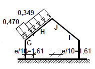
- Roof geometry: Duo‑pitched roof; dimensions: b = 16.1 m, d = 10.9 m, pitch angle α = 39.0°
- Building height: h = 8.2 m
- Reference distance: e = min(b, 2⋅h) = 16.1 m
- Wind direction: Wind on the side wall, θ = 0°
- Fundamental value of basic wind velocity (vb,0) according to the National Annex:
Wind zone 3; Altitude A = 300 m above sea level → vb,0 = 22 m/s - Directional factor: cdir = 1.0
- Season factor: cseason = 1.00
- Basic wind velocity: vb = cdir ⋅ cseason ⋅ vb,0 = 22.00 m/s
- Reference height: ze = h = 8.20 m
- Terrain category II → Roughness factor:
cr(ze) = 1.0 ⋅ (8.2 / 10)0.17 = 0.97 (acc. to National Annex NA.6) - Orography factor: co(ze) = 1.00
- Mean wind velocity: vm(ze) = cr(ze) ⋅ co(ze) ⋅ vb = 21.27 m/s
- Turbulence intensity: Iv(ze) = 0.196
- Air density: ρ = 1.25 kg/m³
- Peak velocity pressure:
qp(ze) = [1 + 7⋅Iv(ze)] ⋅ (1/2) ⋅ ρ ⋅ vm²(ze) = 670.9 Pa = 0.671 kN/m² - Structural factor: cs⋅cd = 1.000
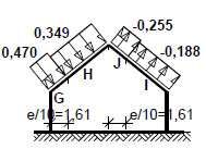
Roof slope in section x/b = 0.50 - Zone G - Pressure:
- External pressure coefficient: cpe = cpe,10 = 0.7
Wind pressure on external surfaces:
Fw,e = cs × cd × qp(ze) × cpe = 1.000 × 0.671 × 0.7 = 0.470 kN/m²
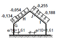
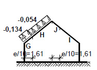
Roof slope in section x/b = 0.50 - Zone G - Suction:
- External pressure coefficient: cpe = cpe,10 = −0.200
Wind suction on external surfaces:
Fw,e = cs × cd × qp(ze) × cpe = 1.000 × 0.671 × (−0.200) = −0.134 kN/m²
Roof slope in section x/b = 0.50 - Zone H - Pressure:
- External pressure coefficient: cpe = cpe,10 = 0.520
Wind pressure on external surfaces:
Fw,e = cs × cd × qp(ze) × cpe = 1.000 × 0.671 × 0.520 = 0.349 kN/m²
Roof slope in section x/b = 0.50 - Zone H - Suction:
- External pressure coefficient: cpe = cpe,10 = −0.080
Wind suction on external surfaces:
Fw,e = cs × cd × qp(ze) × cpe = 1.000 × 0.671 × (−0.080) = −0.054 kN/m²
Roof slope in section x/b = 0.50 - Zone I - Pressure:
- External pressure coefficient: cpe = cpe,10 = 0.0
Wind pressure on external surfaces:
Fw,e = cs × cd × qp(ze) × cpe = 1.000 × 0.671 × 0.0 = 0.000 kN/m²
Roof slope in section x/b = 0.50 - Zone I - Suction:
- External pressure coefficient: cpe = cpe,10 = −0.280
Wind suction on external surfaces:
Fw,e = cs × cd × qp(ze) × cpe = 1.000 × 0.671 × (−0.280) = −0.188 kN/m²
Roof slope in section x/b = 0.50 - Zone J - Pressure:
- External pressure coefficient: cpe = cpe,10 = 0.0
Wind pressure on external surfaces:
Fw,e = cs × cd × qp(ze) × cpe = 1.000 × 0.671 × 0.0 = 0.000 kN/m²
Roof slope in section x/b = 0.50 - Zone J - Suction:
- External pressure coefficient: cpe = cpe,10 = −0.380
Wind suction on external surfaces:
Fw,e = cs × cd × qp(ze) × cpe = 1.000 × 0.671 × (−0.380) = −0.255 kN/m²
III. Structural analysis and design calculations
Item 1. Roof structure
Item 1.1. Rafter 8.5/20 cm
Rafter 8.5/20 cm (notching: wall plate – 3 cm, collar tie – none)
Solid softwood according to EN 338:2004, strength class C24
fm,k=24 MPa,ft,0,k=14 MPa,fc,0,k=21 MPa,fv,k=2.5 MPa,E0,mean=11 GPa,ρk=350 kg/m3
Slenderness ratio:
λy=60.5<150
λz=142.3<150
Maximum forces and stresses in the span
Governing load combination: K15 Permanent-max + Snow + 0.90 · Variable (collar tie) + 0.80 · Wind (right) – variant II
M = −1.58 kNm, N = 18.28 kN
fm,y,d = 11.08 MPa, fc,0,d = 9.69 MPa
σm,y,d = 2.78 MPa, σc,0,d = 1.08 MPa
Instability factors: kc,y = 0.708, kc,z = 0.159
σc,0,d / (kc,y · fc,0,d) + σm,y,d / fm,y,d = 0.408 < 1
σc,0,d / (kc,z · fc,0,d) + σm,y,d / fm,y,d = 0.948 < 1
Maximum forces and stresses at the support – Wall plate
Governing load combination: K10 Permanent-max + Snow + 0.90 · Wind (right) – variant II + 0.80 · Variable (collar tie)
M = −0.95 kNm, N = 21.26 kN
fm,y,d = 11.08 MPa, fc,0,d = 9.69 MPa
σm,y,d = 2.33 MPa, σc,0,d = 1.47 MPa
(σc,0,d / fc,0,d)² + σm,y,d / fm,y,d = 0.234 < 1
Maximum forces and stresses at the support – Collar tie
Governing load combination: K10 (as above)
M = −1.60 kNm, N = 18.06 kN
fm,y,d = 11.08 MPa, fc,0,d = 9.69 MPa
σm,y,d = 2.83 MPa, σc,0,d = 1.06 MPa
(σc,0,d / fc,0,d)² + σm,y,d / fm,y,d = 0.268 < 1
Maximum deflection of the rafter (between collar tie and ridge)
Governing load combination: K2 Permanent-max + Snow
ufin = 2.66 mm < unet,fin = L/200 = 3493/200 = 17.46 mm (15.2%)
Maximum deflection of the rafter cantilever (eave part)
Governing load combination: K2 Permanent-max + Snow
ufin = 0.74 mm < unet,fin = 2 × L/200 = 2 × 1159/200 = 11.59 mm (6.4%)
Item 1.2. Collar Tie
Collar tie 2× 8/20 cm with spacers every 183 cm, made of C24 timber.
Solid softwood according to EN 338:2004, strength class C24.
fm,k = 24 MPa, ft,0,k = 14 MPa, fc,0,k = 21 MPa, fv,k = 2.5 MPa, E0,mean = 11 GPa, ρk = 350 kg/m³
Slenderness ratio:
λy = 94.7 < 150
λz = 170.2 < 175
Maximum forces and stresses:
Governing load combination: K65 Permanent-max + Variable (collar tie) + 0.90 · Snow + 0.80 · Wind (left) – variant II.
M = 5.32 kNm, N = 14.52 kN
fm,y,d = 11.08 MPa, fc,0,d = 9.69 MPa
σm,y,d = 4.98 MPa, σc,0,d = 0.45 MPa
kc,y = 0.343, kc,z = 0.113 σc,0,d / (kc,y · fc,0,d) + σm,y,d / fm,y,d = 0.586 < 1
σc,0,d / (kc,z · fc,0,d) + σm,y,d / fm,y,d = 0.865 < 1
Maximum deflection:
Governing load combination: K62 Permanent-max + Variable (collar tie).
ufin = 15.50 mm < unet,fin = L/200 = 5429/200 = 27.14 mm (57.1%)
Item 1.3. Wall Plate 16/16 cm
Solid softwood according to EN 338:2004, strength class C24.
fm,k = 24 MPa, ft,0,k = 14 MPa, fc,0,k = 21 MPa, fv,k = 2.5 MPa, E0,mean = 11 GPa, ρk = 350 kg/m³
Wall plate section supported on the wall
Extreme design loads:
qz,max = 21.49 kN/m, qy,max = −18.97 kN/m
Maximum forces and stresses:
Governing load combination: K29 Permanent-max + Snow (variant II) + 0.90 · Variable (collar tie) + 0.80 · Wind (right) – variant II.
Mz = 4.57 kNm
fm,z,d = 11.08 MPa, σm,z,d = 6.698 MPa
σm,z,d / fm,z,d = 0.605 < 1
Cantilevered section of the wall plate
Extreme design loads:
qz,max = 21.49 kN/m, qy,max = −18.97 kN/m
Maximum forces and stresses:
Governing load combination: K29 Permanent-max + Snow (variant II) + 0.90 · Variable (collar tie) + 0.80 · Wind (right) – variant II.
My = 2.69 kNm, Mz = 2.37 kNm
fm,y,d = 11.08 MPa, fm,z,d = 11.08 MPa
σm,y,d = 3.93 MPa, σm,z,d = 3.47 MPa
Redistribution factor: km = 0.7 σm,y,d / fm,y,d + km · σm,z,d / fm,z,d = 0.575 < 1
km · σm,y,d / fm,y,d + σm,z,d / fm,z,d = 0.562 < 1
Maximum deflection:
Governing load combination: K16 Permanent-max + Snow (variant II).
ufin = 0.35 mm < unet,fin = 2 × L/200 = 2 × 500/200 = 5.00 mm ( 7.1%)
Item 1.4. Bracing Purlin 16/16 cm
Adopted for structural reasons (nominal size).
Item 1.5. Bracing Purlin 16/16 cm
Adopted for structural reasons (nominal size).
Item 1.6. Valley Rafter 14/20 cm
Bending:
Governing combination A: Permanent max + Insulation + Snow + Wind.
Design moments:
Span moment: Mspan = 7.68 kNm
Support moment: Msupport = −0.72 kNm
Load-bearing capacity check – Span
σm,y,d = 8.23 MPa, fm,y,d = 11.08 MPa
σm,y,d / fm,y,d = 0.743 < 1
Load-bearing capacity check – Support
σm,y,d = 1.06 MPa, fm,y,d = 11.08 MPa
σm,y,d / fm,y,d = 0.096 < 1
Deflection (Cantilever):
ufin = (−)11.03 mm < unet,fin = 2.0 × L/200 = 11.41 mm (96.7%)
Deflection (Mid-span):
ufin = 14.95 mm < unet,fin = L/200 = 21.19 mm (70.6%)
Item 1.7. Rafter 8/20 cm
Rafter 8/20 cm (notching: wall plate – 3 cm, collar tie – none).
Solid softwood according to EN 338:2004, strength class C24.
fm,k = 24 MPa, ft,0,k = 14 MPa, fc,0,k = 21 MPa, fv,k = 2.5 MPa, E0,mean = 11 GPa, ρk = 350 kg/m³
Slenderness ratio:
λy = 38.4 < 150
λz = 90.4 < 150
Maximum forces and stresses in the span:
Governing combination: K24 Permanent-max + Snow (var. II) + 0.90 · Wind (right, var. II) + 0.80 · Variable (collar tie).
M = −0.74 kNm, N = 6.48 kN
fm,y,d = 11.08 MPa, fc,0,d = 9.69 MPa
σm,y,d = 1.30 MPa, σc,0,d = 0.38 MPa
Instability factors: kc,y = 0.952, kc,z = 0.373 σc,0,d / (kc,y · fc,0,d) + σm,y,d / fm,y,d = 0.159 < 1
σc,0,d / (kc,z · fc,0,d) + σm,y,d / fm,y,d = 0.223 < 1
Maximum forces and stresses at the support – Wall plate:
Governing combination: K56 Permanent-max + Wind (right, var. II) + 0.90 · Snow + 0.80 · Variable (collar tie).
M = −0.56 kNm, N = 8.38 kN
(σc,0,d / fc,0,d)² + σm,y,d / fm,y,d = 0.127 < 1
Maximum forces and stresses at the support – Collar tie:
Governing combination: K23 Permanent-max + Snow (var. II) + 0.90 · Wind (right, var. II).
M = −0.74 kNm, N = 6.03 kN
(σc,0,d / fc,0,d)² + σm,y,d / fm,y,d = 0.119 < 1
Maximum deflection (between wall plate and collar tie):
ufin = 0.45 mm < unet,fin = L/200 = 2218/200 = 11.09 mm (4.0%)
Maximum deflection of the rafter cantilever:
Governing combination: K85 Permanent-max + Assembly load (collar tie).
ufin = 0.30 mm < unet,fin = 2 × L/200 = 2 × 902/200 = 9.02 mm (3.3%)
Item 1.9. Collar Tie 8/20 cm
Collar tie 8/20 cm made of C24 timber.
Solid softwood according to EN 338:2004, strength class C24.
fm,k = 24 MPa, ft,0,k = 14 MPa, fc,0,k = 21 MPa, fv,k = 2.5 MPa, E0,mean = 11 GPa, ρk = 350 kg/m³
Slenderness ratio:
λy = 18.7 < 150
λz = 44.0 < 150
Maximum forces and stresses:
Governing load combination: K85 Permanent-max + Assembly load (collar tie).
M = 0.41 kNm, N = 4.15 kN
fm,y,d = 12.92 MPa, fc,0,d = 11.31 MPa
σm,y,d = 0.72 MPa, σc,0,d = 0.24 MPa
Instability factor: kc,z = 0.910 (σc,0,d / fc,0,d)² + σm,y,d / fm,y,d = 0.056 < 1
σc,0,d / (kc,z · fc,0,d) + σm,y,d / fm,y,d = 0.079 < 1
Maximum deflection:
Governing load combination: K85 Permanent-max + Assembly load (collar tie).
ufin = 0.08 mm < unet,fin = L/200 = 1041/200 = 5.21 mm (1.5%)
Item 1.10. Ridge Purlin
Adopted for structural reasons (nominal size).
Item 2.Attic structure
Item 2.1. Column 25/25 cm
Combined compression and bending:
Symmetric reinforcement along "b" sides adopted:
Required reinforcement: 3φ16 (As = 6.03 cm²) per side.
Symmetric reinforcement along "h" sides adopted:
Required reinforcement: 2φ16 (As = 4.02 cm²) per side.
Total reinforcement adopted: 6φ16 (As = 12.06 cm², ρ = 1.93%).
Load-bearing capacity check (ULS):
For Nd = 38.95 kN: Md,x = 41.52 kNm < MRd,x,max = 47.35 kNm
For Md,x = 41.52 kNm: Nd = 38.95 kN < NRd,max = 842.97 kN
Structural stirrups (Ties):
Structural reinforcement with single stirrups:
Outside the lap zones of main bars: φ6 every max. 240 mm.
Within the lap zones of main bars: φ6 every max. 120 mm.
Serviceability Limit State (SLS):
Characteristic moments: MSk = 33.67 kNm, MSk,lt = 33.67 kNm
Characteristic forces: NSk = 32.18 kN, NSk,lt = 33.85 kN
Crack width (perpendicular): wk = 0.211 mm < wlim = 0.3 mm (70.4%)
Item 2.2. Column Ø25 cm (Circular)
Combined compression and bending:
Total reinforcement adopted by user: 8φ12 (As = 9.05 cm², ρ = 1.84%).
Load-bearing capacity check (ULS):
For Nd = 21.50 kN: Md,x = 0.24 kNm < MRd,x,max = 27.78 kNm
For Md,x = 0.24 kNm: Nd = 21.50 kN < NRd,max = 1010.38 kN
Structural stirrups:
Outside lap zones: φ6 every max. 180 mm.
Within lap zones: φ6 every max. 90 mm.
SLS:
Crack width not determined.
Item 2.3. Arched Lintel 25x25 cm
Bending (Section a-a):
Design span moment: MSd = 13.64 kNm
Required bottom reinforcement: As1 = 1.64 cm². Adopted 2φ12 (As = 2.26 cm², ρ = 0.43%).
Bending capacity check: MSd = 13.64 kNm < MRd = 18.41 kNm (74.1%)
Shear:
Design shear force: VSd = 17.79 kN
Structural reinforcement: double-leg stirrups φ6 every 150 mm along the entire span.
Shear capacity check: VSd = 17.79 kN < VRd1 = 34.81 kN (51.1%)
SLS:
Crack width (perpendicular): wk = 0.204 mm < wlim = 0.3 mm (68.1%)
Max. deflection from MSk,lt: a(MSk,lt) = 3.69 mm < alim = L/200 = 10.45 mm (35.4%)
Item 2.4. Lintel 25x25 cm
Bending (Section a-a):
Design span moment: MSd = 32.18 kNm
Required bottom reinforcement: As1 = 4.22 cm². Adopted 4φ12 (As = 4.52 cm², ρ = 0.87%).
Bending capacity check: MSd = 32.18 kNm < MRd = 34.11 kNm (94.4%)
Shear:
Design shear force: VSd = 40.28 kN
Stirrups: double-leg φ6 every 140 mm on a 42.0 cm section at supports, and every 150 mm at mid-span.
(Governing condition: limiting width of inclined cracks).
Shear capacity check: VSd = 40.28 kN < VRd3 = 63.52 kN (63.4%)
SLS:
Crack width (perpendicular): wk = 0.200 mm < 0.3 mm
Max. deflection: 7.24 mm < 11.25 mm
Crack width (inclined): wk = 0.265 mm < wlim = 0.3 mm (88.4%)
Item 2.5. Arched Lintel 25x25 cm
Bending (Section a-a):
Design span moment: MSd = 18.40 kNm
Required bottom reinforcement: As1 = 2.26 cm²
Adopted: 3φ12 (As = 3.39 cm², ρ = 0.65%)
(Governing condition: allowable width of perpendicular cracks)
Bending capacity check: MSd = 18.40 kNm < MRd = 26.59 kNm (69.2%)
Shear:
Design shear force: VSd = 19.09 kN
Structural reinforcement: double-leg φ6 stirrups every 150 mm along the entire span
Shear capacity check: VSd = 19.09 kN < VRd1 = 37.01 kN (51.6%)
SLS:
Characteristic span moment: MSk = 13.00 kNm
Long-term characteristic moment: MSk,lt = 13.00 kNm
Perpendicular crack width: wk = 0.160 mm < wlim = 0.3 mm (53.4%)
Maximum deflection from MSk,lt: a(MSk,lt) = 8.36 mm < alim = 3000/200 = 15.00 mm (55.7%)
Characteristic shear force: VSk,lt = 15.89 kN
Inclined crack width: not determined
Item 2.6. Arched Lintel 25x25 cm
Bending (Section a-a):
Design span moment: MSd = 17.31 kNm
Required bottom reinforcement: As1 = 2.12 cm²
Adopted: 2φ12 (As = 2.26 cm², ρ = 0.43%)
Bending capacity check: MSd = 17.31 kNm < MRd = 18.41 kNm (94.0%)
Shear:
Design shear force: VSd = 25.02 kN
Structural reinforcement: double-leg φ6 stirrups every 150 mm along the entire span
Shear capacity check: VSd = 25.02 kN < VRd1 = 34.81 kN (71.9%)
SLS:
Characteristic span moment: MSk = 12.44 kNm
Long-term characteristic moment: MSk,lt = 12.44 kNm
Perpendicular crack width: wk = 0.289 mm < wlim = 0.3 mm (96.2%)
Maximum deflection from MSk,lt: a(MSk,lt) = 3.14 mm < alim = 1650/200 = 8.25 mm (38.0%)
Characteristic shear force: VSk,lt = 25.59 kN
Inclined crack width: not determined
Item 2.7. Ring Beam 25x25 cm
dopted for structural reasons: 3ϕ12 on each side, stirrups ϕ6 every 25 cm.
Item 3. Floor slab over the ground floor, h=18 cm

Item 3.2. Main Beam 25x56 cm
Bending (Section a-a):
Design span moment: MSd = 37.63 kNm
Required bottom reinforcement: As1 = 1.77 cm². Adopted 2φ12 (As = 2.26 cm², ρ = 0.17%)
Bending capacity check: MSd = 37.63 kNm < MRd = 47.86 kNm (78.6%)
Shear:
Design shear force: VSd = (−)28.64 kN
Structural reinforcement: double-leg φ6 stirrups every 380 mm along the entire span
Shear capacity check: VSd = (−)28.64 kN < VRd1 = 62.28 kN (46.0%)
SLS (Serviceability Limit State):
Characteristic span moment: MSk = 26.61 kNm
Quasi-permanent characteristic span moment: MSk,lt = 26.61 kNm
Perpendicular crack width: not determined (Mcr > MSk) – section remains uncracked
Max. deflection from MSk,lt: a(MSk,lt) = 0.83 mm < alim = L/200 = 15.05 mm (5.5%)
Governing characteristic shear force: VSk,lt = 32.43 kN
Inclined crack width: not determined
Item 3.3. Main Beam 25x56 cm
Bending (Section a-a):
Design span moment: MSd = 3.37 kNm
Required bottom reinforcement (structural minimum): As1 = 1.68 cm². Adopted 2φ12 (As = 2.26 cm², ρ = 0.17%)
Bending capacity check: MSd = 3.37 kNm < MRd = 47.86 kNm (7.0%)
Shear:
Design shear force: VSd = (−)4.06 kN
Structural reinforcement: double-leg φ6 stirrups every 380 mm along the entire span
Shear capacity check: VSd = (−)4.06 kN < VRd1 = 62.28 kN (6.5%)
SLS (Serviceability Limit State):
Characteristic span moment: MSk = 2.46 kNm
Quasi-permanent characteristic span moment: MSk,lt = 2.46 kNm
Perpendicular crack width: not determined (Mcr > MSk)
Max. deflection from MSk,lt: a(MSk,lt) = 0.01 mm < alim = L/200 = 7.05 mm (0.2%)
Governing characteristic shear force: VSk,lt = 10.49 kN
Inclined crack width: not determined
Bending (Section b-b):
Design support moment: MSd = (−)4.00 kNm
Required top reinforcement (structural minimum): As1 = 1.68 cm². Adopted 2φ12 (As = 2.26 cm², ρ = 0.17%)
Bending capacity check: MSd = (−)4.00 kNm < MRd = 47.86 kNm (8.4%)
SLS (Support):
Characteristic support moment: MSk = (−)2.93 kNm
Quasi-permanent characteristic support moment: MSk,lt = (−)2.93 kNm
Perpendicular crack width: not determined (Mcr > MSk)
Item 3.4. Main Beam 25x62 cm
Bending (Section a-a):
Design span moment: MSd = 13.51 kNm
Required bottom reinforcement (structural minimum): As1 = 1.88 cm². Adopted 2φ12 (As = 2.26 cm², ρ = 0.16%)
Bending capacity check: MSd = 13.51 kNm < MRd = 53.56 kNm (25.2%)
Shear:
Design shear force: VSd = 6.48 kN
Structural reinforcement: double-leg φ6 stirrups every 400 mm along the entire span
Shear capacity check: VSd = 6.48 kN < VRd1 = 65.26 kN (9.9%)
SLS:
Characteristic span moment: MSk = 9.56 kNm
Quasi-permanent characteristic span moment: MSk,lt = 9.56 kNm
Perpendicular crack width: not determined (Mcr > MSk)
Max. deflection from MSk,lt: a(MSk,lt) = 0.08 mm < alim = L/200 = 8.95 mm (0.9%)
Governing characteristic shear force: VSk,lt = 18.39 kN
Inclined crack width: not determined
Item 3.5. Main Beam 25x62 cm
Bending (Section a-a):
Design span moment: MSd = 34.98 kNm
Required bottom reinforcement (structural minimum): As1 = 1.88 cm². Adopted 2φ12 (As = 2.26 cm², ρ = 0.16%)
Bending capacity check: MSd = 34.98 kNm < MRd = 53.56 kNm (65.3%)
Shear:
Design shear force: VSd = (−)24.86 kN
Structural reinforcement: double-leg φ6 stirrups every 400 mm along the entire span
Shear capacity check: VSd = (−)24.86 kN < VRd1 = 65.26 kN (38.1%)
SLS:
Characteristic span moment: MSk = 24.76 kNm
Quasi-permanent characteristic span moment: MSk,lt = 24.76 kNm
Perpendicular crack width: not determined (Mcr > MSk)
Max. deflection from MSk,lt: a(MSk,lt) = 0.52 mm < alim = L/200 = 14.40 mm (3.6%)
Governing characteristic shear force: VSk,lt = 31.40 kN
Inclined crack width: not determined
Item 4. Internal stairs
Item 4.1. Slab thickness h = 18 cm
Bending (Section a-a):
Design span moment: MSd = 19.41 kNm/m
Required reinforcement: As = 3.38 cm²/m.
Adopted: φ16 every 15.0 cm (As = 13.40 cm²/m, ρ = 0.94%)
(Note: bar spacing adopted by user)
Bending capacity check: MSd = 19.41 kNm/m < MRd = 68.06 kNm/m (28.5%)
Shear:
Design shear force: VSd = 22.33 kN/m
Shear capacity check: VSd = 22.33 kN/m < VRd1 = 65.89 kN/m (33.9%)
SLS (Serviceability Limit State):
Characteristic span moment: MSk = 15.84 kNm/m
Quasi-permanent characteristic span moment: MSk,lt = 13.20 kNm/m
Perpendicular crack width: wk = 0.069 mm < wlim = 0.3 mm (23.0%)
Max. deflection from MSk,lt: a(MSk,lt) = 5.53 mm < alim = L/200 = 16.75 mm (33.0%)
Item 4.2. Slab thickness h = 18 cm
Bending (Section a-a):
Design span moment: MSd = 41.16 kNm/m
Required reinforcement: As = 7.53 cm²/m.
Adopted: φ16 every 10.0 cm (As = 20.11 cm²/m, ρ = 1.42%)
(Note: bar spacing adopted by user)
Bending capacity check: MSd = 41.16 kNm/m < MRd = 93.17 kNm/m (44.2%)
Shear:
Design shear force: VSd = 33.76 kN/m
Shear capacity check: VSd = 33.76 kN/m < VRd1 = 69.01 kN/m (48.9%)
SLS:
Characteristic span moment: MSk = 33.59 kNm/m
Quasi-permanent characteristic span moment: MSk,lt = 28.01 kNm/m
Perpendicular crack width: wk = 0.118 mm < wlim = 0.3 mm (39.2%)
Max. deflection from MSk,lt: a(MSk,lt) = 23.18 mm < alim = L/200 = 24.15 mm (96.0%)
Item 5. Ground floor structure
Item 5.1. Beam 25x42 cm
Bending (Section a-a):
Design span moment: MSd = 35.90 kNm
Required bottom reinforcement: As1 = 2.35 cm². Adopted 3φ12 (As = 3.39 cm², ρ = 0.36%)
Bending capacity check: MSd = 35.90 kNm < MRd = 50.82 kNm (70.6%)
Shear:
Design shear force: VSd = 34.94 kN
Structural reinforcement: double-leg φ6 stirrups every 280 mm along the entire span
Shear capacity check: VSd = 34.94 kN < VRd1 = 54.31 kN (64.3%)
SLS:
Characteristic span moment: MSk = 25.29 kNm
Long-term characteristic moment: MSk,lt = 25.29 kNm
Perpendicular crack width: wk = 0.203 mm < wlim = 0.3 mm (67.8%)
Maximum deflection from MSk,lt: a(MSk,lt) = 2.31 mm < alim = 2350/200 = 11.75 mm (19.6%)
Characteristic shear force: VSk,lt = 38.46 kN
Inclined crack width: not determined
Item 5.2. Beam 25x42 cm
Bending (Section a-a):
Design span moment: MSd = 11.50 kNm
Required bottom reinforcement (structural minimum): As1 = 1.23 cm². Adopted 2φ12 (As = 2.26 cm², ρ = 0.24%)
Bending capacity check: MSd = 11.50 kNm < MRd = 34.56 kNm (33.3%)
Shear:
Design shear force: VSd = 8.42 kN
Structural reinforcement: double-leg φ6 stirrups every 280 mm along the entire span
Shear capacity check: VSd = 8.42 kN < VRd1 = 52.37 kN (16.1%)
SLS:
Characteristic span moment: MSk = 8.10 kNm
Long-term characteristic moment: MSk,lt = 8.10 kNm
Perpendicular crack width: not determined (Mcr > MSk)
Maximum deflection from MSk,lt: a(MSk,lt) = 0.12 mm < alim = 1330/200 = 6.65 mm (1.8%)
Characteristic shear force: VSk,lt = 19.78 kN
Inclined crack width: not determined
Item 5.3. Beam 25x42 cm
Bending (Section a-a):
Design span moment: MSd = 28.12 kNm
Required bottom reinforcement: As1 = 1.83 cm². Adopted 2φ12 (As = 2.26 cm², ρ = 0.24%)
Bending capacity check: MSd = 28.12 kNm < MRd = 34.56 kNm (81.4%)
Shear:
Design shear force: VSd = 27.92 kN
Structural reinforcement: double-leg φ6 stirrups every 280 mm along the entire span
Shear capacity check: VSd = 27.92 kN < VRd1 = 52.37 kN (53.3%)
SLS:
Characteristic span moment: MSk = 19.81 kNm
Long-term characteristic moment: MSk,lt = 19.81 kNm
Perpendicular crack width: wk = 0.271 mm < wlim = 0.3 mm (90.3%)
Maximum deflection from MSk,lt: a(MSk,lt) = 1.69 mm < alim = 2080/200 = 10.40 mm (16.3%)
Characteristic shear force: VSk,lt = 33.51 kN
Inclined crack width: not determined
Item 5.4. Beam 25x42 cm
Bending (Section a-a):
Design span moment: MSd = 6.63 kNm
Required bottom reinforcement (structural minimum): As1 = 1.23 cm². Adopted: 2φ12 (As = 2.26 cm², ρ = 0.24%)
Bending capacity check: MSd = 6.63 kNm < MRd = 34.56 kNm (19.2%)
Shear:
Design shear force: VSd = 0.10 kN
Structural reinforcement: double-leg φ6 stirrups every 280 mm along the entire span
Shear capacity check: VSd = 0.10 kN < VRd1 = 52.37 kN (0.2%)
SLS:
Characteristic span moment: MSk = 4.67 kNm
Long-term characteristic moment: MSk,lt = 4.67 kNm
Perpendicular crack width: not determined (Mcr > MSk)
Maximum deflection from MSk,lt: a(MSk,lt) = 0.04 mm < alim = 1010/200 = 5.05 mm (0.8%)
Characteristic shear force: VSk,lt = 13.92 kN
Inclined crack width: not determined
Item 5.5. Beam 25x42 cm
Bending (Section a-a):
Design span moment: MSd = 10.96 kNm
Required bottom reinforcement (structural minimum): As1 = 2.14 cm². Adopted: 2φ12 (As = 2.26 cm², ρ = 0.14%)
Bending capacity check: MSd = 10.96 kNm < MRd = 61.16 kNm (17.9%)
Shear:
Design shear force: VSd = 8.05 kN
Structural reinforcement: double-leg φ6 stirrups every 400 mm along the entire span
Shear capacity check: VSd = 8.05 kN < VRd1 = 72.26 kN (11.1%)
SLS:
Characteristic span moment: MSk = 7.74 kNm
Long-term characteristic moment: MSk,lt = 7.74 kNm
Perpendicular crack width: not determined (Mcr > MSk)
Maximum deflection from MSk,lt: a(MSk,lt) = 0.02 mm < alim = 1270/200 = 6.35 mm (0.3%)
Characteristic shear force: VSk,lt = 19.57 kN
Inclined crack width: not determined
Item 5.6. Beam 25x25 cm
Bending (Section a-a):
Design span moment: MSd = 24.03 kNm
Required bottom reinforcement: As1 = 3.03 cm². Adopted: 3φ12 (As = 3.39 cm², ρ = 0.65%)
Bending capacity check: MSd = 24.03 kNm < MRd = 26.59 kNm (90.4%)
Shear:
Design shear force: VSd = (−)32.46 kN
Structural reinforcement: double-leg φ6 stirrups every 150 mm along the entire span
Shear capacity check: VSd = (−)32.46 kN < VRd1 = 37.01 kN (87.7%)
SLS:
Characteristic span moment: MSk = 16.90 kNm
Long-term characteristic moment: MSk,lt = 16.90 kNm
Perpendicular crack width: wk = 0.217 mm < wlim = 0.3 mm (72.4%)
Maximum deflection from MSk,lt: a(MSk,lt) = 4.69 mm < alim = 1950/200 = 9.75 mm (48.1%)
Characteristic shear force: VSk,lt = 30.22 kN
Inclined crack width: not determined
Item 5.7. Beam 25x25 cm
Bending (Section a-a):
Design span moment: MSd = 19.35 kNm
Required bottom reinforcement: As1 = 2.39 cm². Adopted: 3φ12 (As = 3.39 cm², ρ = 0.65%)
Bending capacity check: MSd = 19.35 kNm < MRd = 26.59 kNm (72.8%)
Shear:
Design shear force: VSd = (−)27.40 kN
Structural reinforcement: double-leg φ6 stirrups every 150 mm along the entire span
Shear capacity check: VSd = (−)27.40 kN < VRd1 = 37.01 kN (74.0%)
SLS:
Characteristic span moment: MSk = 13.61 kNm
Long-term characteristic moment: MSk,lt = 13.61 kNm
Perpendicular crack width: wk = 0.169 mm < wlim = 0.3 mm (56.4%)
Maximum deflection from MSk,lt: a(MSk,lt) = 2.99 mm < alim = 1750/200 = 8.75 mm (34.2%)
Characteristic shear force: VSk,lt = 26.67 kN
Inclined crack width: not determined
Item 5.8. Beam 25x25 cm
Bending (Section a-a):
Design span moment: MSd = 31.99 kNm
Required bottom reinforcement: As1 = 4.20 cm². Adopted: 4φ12 (As = 4.52 cm², ρ = 0.87%)
Bending capacity check: MSd = 31.99 kNm < MRd = 34.11 kNm (93.8%)
Shear:
Design shear force: VSd = 40.04 kN
Structural reinforcement: double-leg φ6 stirrups every 150 mm on a 45.0 cm section near supports and every 150 mm at mid-span
Shear capacity check: VSd = 40.04 kN < VRd3 = 59.28 kN (67.5%)
SLS:
Characteristic span moment: MSk = 22.50 kNm
Long-term characteristic moment: MSk,lt = 22.50 kNm
Perpendicular crack width: wk = 0.194 mm < wlim = 0.3 mm (64.8%)
Maximum deflection from MSk,lt: a(MSk,lt) = 7.04 mm < alim = 2250/200 = 11.25 mm (62.5%)
Characteristic shear force: VSk,lt = 35.56 kN
Inclined crack width: wk = 0.288 mm < wlim = 0.3 mm (96.0%)
Item 5.9. Beam 25x25 cm
Bending (Section a-a):
Design span moment: MSd = 8.65 kNm
Required bottom reinforcement: As1 = 1.02 cm². Adopted: 2φ12 (As = 2.26 cm², ρ = 0.43%)
Bending capacity check: MSd = 8.65 kNm < MRd = 18.41 kNm (47.0%)
Shear:
Design shear force: VSd = 12.74 kN
Structural reinforcement: double-leg φ6 stirrups every 150 mm along the entire span
Shear capacity check: VSd = 12.74 kN < VRd1 = 34.81 kN (36.6%)
SLS:
Characteristic span moment: MSk = 6.08 kNm
Long-term characteristic moment: MSk,lt = 6.08 kNm
Perpendicular crack width: wk = 0.088 mm < wlim = 0.3 mm (29.3%)
Maximum deflection from MSk,lt: a(MSk,lt) = 0.60 mm < alim = 1170/200 = 5.85 mm (10.3%)
Characteristic shear force: VSk,lt = 16.35 kN
Inclined crack width: not determined
Item 5.10. Beam 25x25 cm
Bending (Section a-a):
Design span moment: MSd = 64.98 kNm
Required bottom reinforcement: As1 = 5.68 cm². Adopted: 6φ12 (As = 6.79 cm², ρ = 0.88%)
Bending capacity check: MSd = 64.98 kNm < MRd = 75.60 kNm (86.0%)
Shear:
Design shear force: VSd = (−)59.48 kN
Structural reinforcement: double-leg φ6 stirrups every 150 mm on a 60.0 cm section near supports and every 230 mm at mid-span
(Governing condition: limiting width of inclined cracks)
Shear capacity check: VSd = (−)59.48 kN < VRd3 = 87.78 kN (67.8%)
SLS:
Characteristic span moment: MSk = 45.75 kNm
Long-term characteristic moment: MSk,lt = 45.75 kNm
Perpendicular crack width: wk = 0.171 mm < wlim = 0.3 mm (57.0%)
Maximum deflection from MSk,lt: a(MSk,lt) = 8.69 mm < alim = 3180/200 = 15.90 mm (54.7%)
Characteristic shear force: VSk,lt = 53.01 kN
Inclined crack width: wk = 0.292 mm < wlim = 0.3 mm (97.3%)
Item 5.11. Beam 25x25 cm
Bending (Section a-a):
Design span moment: MSd = 6.45 kNm
Required bottom reinforcement: As1 = 0.76 cm². Adopted: 2φ12 (As = 2.26 cm², ρ = 0.43%)
Bending capacity check: MSd = 6.45 kNm < MRd = 18.41 kNm (35.0%)
Shear:
Design shear force: VSd = (−)8.70 kN
Structural reinforcement: double-leg φ6 stirrups every 150 mm along the entire span
Shear capacity check: VSd = (−)8.70 kN < VRd1 = 34.81 kN (25.0%)
SLS:
Characteristic span moment: MSk = 4.53 kNm
Long-term characteristic moment: MSk,lt = 4.53 kNm
Perpendicular crack width: not determined (Mcr > MSk)
Maximum deflection from MSk,lt: a(MSk,lt) = 0.18 mm < alim = 1010/200 = 5.05 mm (3.6%)
Characteristic shear force: VSk,lt = 13.51 kN
Inclined crack width: not determined
Item 5.12. Column 25x25 cm
Combined compression and bending:
Symmetric reinforcement along “b” sides:
Required: 2φ16 (As = 4.02 cm²)
Symmetric reinforcement along “h” sides:
Required: 2φ16 (As = 4.02 cm²)
Total adopted: 4φ16 (As = 8.04 cm², ρ = 1.29%)
Load-bearing capacity:
For Nd = 66.81 kN: Md,x = 0.94 kNm < MRd,x,odp,max = 35.97 kNm
For Md,x = 0.94 kNm: Nd = 66.81 kN < NRd,odp,max = 1152.47 kN
Structural stirrups:
Single-leg stirrups:
φ6 every max. 240 mm outside lap zones
φ6 every max. 120 mm within lap zones
SLS:
Perpendicular crack width: wk = 0.000 mm < wlim = 0.3 mm (0.0%)
Item 5.13. Column Ø25 cm
Combined compression and bending:
Total required reinforcement: 6φ16 (As = 12.06 cm², ρ = 2.46%)
Load-bearing capacity:
For Nd = 86.63 kN: Md,x = 1.68 kNm < MRd,x,odp,max = 35.32 kNm
For Md,x = 1.68 kNm: Nd = 86.63 kN < NRd,odp,max = 1121.07 kN
Structural stirrups:
Single-leg stirrups:
φ6 every max. 240 mm outside lap zones
φ6 every max. 120 mm within lap zones
SLS:
Perpendicular crack width: not determined
Item 5.14. Column Ø25 cm
Combined compression and bending:
Total required reinforcement: 6φ16 (As = 12.06 cm², ρ = 2.46%)
Load-bearing capacity:
For Nd = 76.60 kN: Md,x = 1.45 kNm < MRd,x,odp,max = 35.03 kNm
For Md,x = 1.45 kNm: Nd = 76.60 kN < NRd,odp,max = 1124.42 kN
Structural stirrups:
Single-leg stirrups:
φ6 every max. 240 mm outside lap zones
φ6 every max. 120 mm within lap zones
SLS:
Perpendicular crack width: not determined
Item 5.15. Ring Beam 25x25 cm
Reinforcement:
Adopted structurally: 2×φ12 on each side
Stirrups: Ø6 every 25 cm
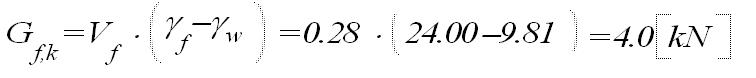
Item 6. Foundation structure
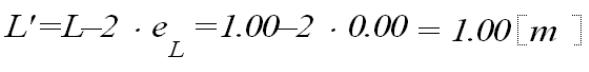
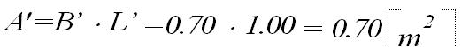
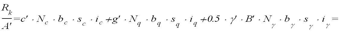
Item 6.1. Foundation strip footing 60x40 cm
| Layer | Soil Name | Thickness [m] | γ [kN/m³] | φ′ [°] | c′ [kPa] | cu [kPa] | M0 [kPa] | M [kPa] |
| 1 | Medium Silt (MSi) | 3.0 | 20.0 | 15.8 | 20.0 | 0.0 | 34065.0 | 56787.0 |
| Parameter | Value | Unit |
| Foundation depth | 1.2 | m |
| Groundwater level | 0.0 | m |
| Backfill unit weight | 18.0 | kN/m³ |
Complete Load Set (ULS/SLS)
Load Set No. 1:
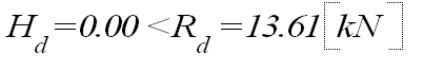
| Name | V [kN] | MB [kNm] | ML [kNm] | HB [kN] | HL [kN] |
| ULS | 100.00 | 0.00 | 0.00 | 0.00 | 0.00 |
| SLS | 70.00 | 0.00 | 0.00 | 0.00 | 0.00 |
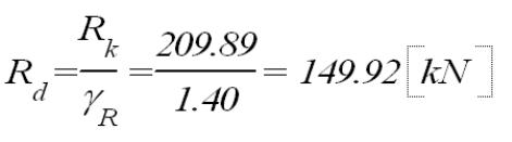
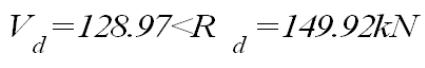
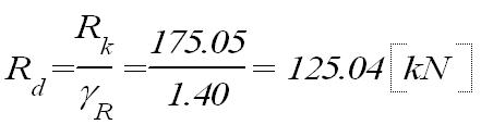
Ultimate Limit State (GEO) Verification:
Design Approach: DA2
Partial factors: γG,unfavorable=1.35, γQ=1.50
γR=1.4 – Partial factor for bearing resistance (against soil expulsion)
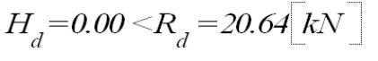
γR,h=1.1 – Partial factor for sliding resistance
Foundation depth (hf): 1.20 m
Vertical bearing capacity check
Condition: "drained"
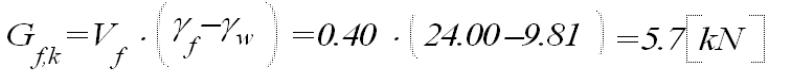
Additional ground loads:
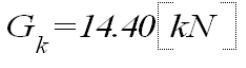
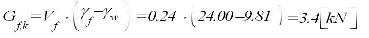
Total weight of the foundation:
Weight of soil over the foundation:
Design value of the ground load:

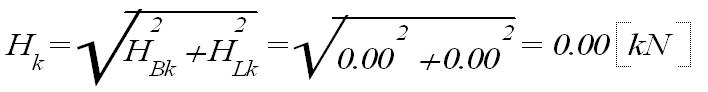
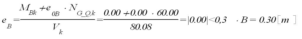
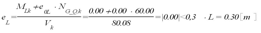
Loads transferred to the ground (characteristic values, moment values excluding the effect of vertical force eccentricity):


Load eccentricity:
Requirement satisfied
Requirement satisfied
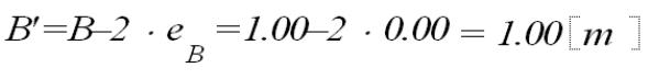
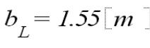
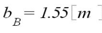
Effective foundation dimensions:


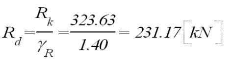
Ultimate bearing capacity:

q – total overburden pressure at the foundation level (adjacent to the footing)

Design verification
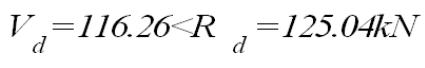
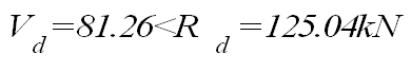
Bearing capacity check satisfied.
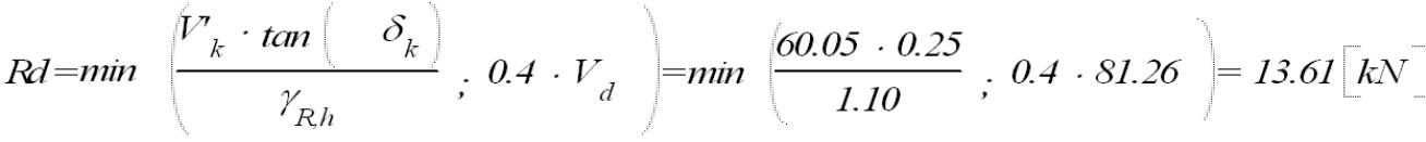
Sliding resistance check at the foundation level

Where:
Hd – design value of the horizontal force transferred from the foundation to the ground.
Rd – design sliding resistance between the foundation base and the ground.
Rp,d – design earth pressure resistance (passive pressure); adopted value = 0.0.
Condition: "drained"
Design value of the ultimate soil resistance beneath the foundation

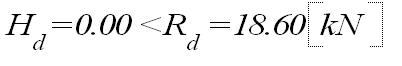
Sliding resistance check satisfied.
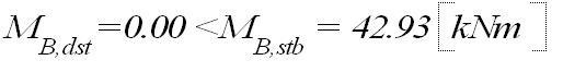
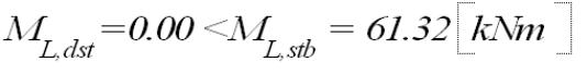
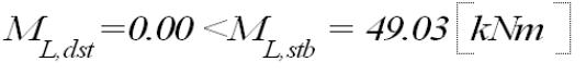
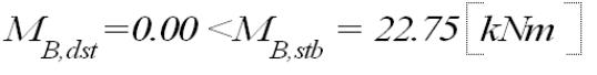
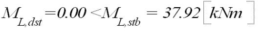
Verification of Foundation Equilibrium (EQU):
Notation:
stb – stabilizing actions
dst – destabilizing actions
Partial factors for actions:
γG,dst=1.10
γG,stb=0.90
γQ,dst=1.50
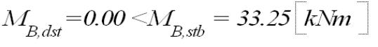
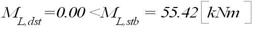
Stability condition satisfied.
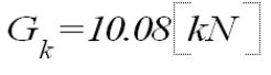
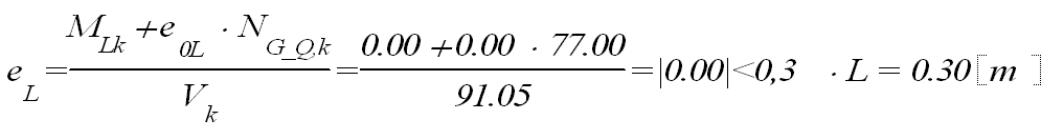
Item 6.2. Foundation strip footing 70x40 cm
Complete Load Set (ULS/SLS)
Load Set No. 1:
| Name | V [kN] | MB [kNm] | ML [kNm] | HB [kN] | HL [kN] |
| ULS | 100.00 | 0.00 | 0.00 | 0.00 | 0.00 |
| SLS | 77.00 | 0.00 | 0.00 | 0.00 | 0.00 |
Ultimate Limit State (GEO) Verification:
Design Approach: DA2
Partial factors: γG,unfavorable=1.35, γQ=1.50
γR=1.4 – Partial factor for bearing resistance (against soil expulsion)
γR,h=1.1 – Partial factor for sliding resistance
Foundation depth (hf): 1.20 m
Vertical bearing capacity check
Condition: "drained"
Additional ground loads:
Total weight of the foundation:
Weight of soil over the foundation:
Design value of the ground load:

Loads transferred to the ground (characteristic values, moment values excluding the effect of vertical force eccentricity):


Load eccentricity:
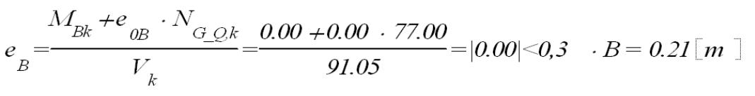
Condition satisfied
Condition satisfied
Effective foundation dimensions:
Ultimate bearing capacity:

q – total overburden pressure at the foundation level (adjacent to the footing)
Design condition
Bearing resistance requirement satisfied.
Sliding resistance check at the foundation level

Where:
Hd – design value of the horizontal force transferred from the foundation to the ground.
Rd – design sliding resistance between the foundation base and the ground.
Rp,d – design earth pressure resistance (passive pressure); adopted value = 0.0.
Condition: "drained"
Design value of the ultimate soil resistance beneath the foundation

Sliding resistance check satisfied.
Verification of Foundation Stability (EQU):
Notation:
stb – stabilizing actions
dst – destabilizing actions
Partial factors for actions:
γG,dst=1.10
γG,stb=0.90
γQ,dst=1.50
Stability condition satisfied.
Item 6.3. Pad Foundation 100x100x40 cm
Complete Load Set (ULS/SLS)
Load Set No. 1:
| Name | V [kN] | MB [kNm] | ML [kNm] | HB [kN] | HL [kN] |
| ULS | 80.00 | 0.00 | 0.00 | 0.00 | 0.00 |
| SLS | 60.00 | 0.00 | 0.00 | 0.00 | 0.00 |
Ultimate Limit State (GEO) Verification:
Design Approach: DA2
Partial factors: γG,unfavorable=1.35, γQ=1.50
γR=1.4 – Partial factor for bearing resistance (against soil expulsion)
γR,h=1.1 – Partial factor for sliding resistance
Foundation depth (hf): 1.20 m
Vertical bearing capacity check
Condition: "drained"
Additional ground loads:
Total weight of the foundation:
Weight of soil over the foundation:
Design value of the ground load:

Loads transferred to the ground (characteristic values, moment values excluding the effect of vertical force eccentricity):


Load eccentricity:
Condition satisfied
Condition satisfied
Effective foundation dimensions:


Ultimate bearing capacity:


q – total overburden pressure at the foundation level (adjacent to the footing)
Design condition
Bearing resistance requirement satisfied.
Sliding resistance check at the foundation level
Where:
Hd – design value of the horizontal force transferred from the foundation to the ground.
Rd – design sliding resistance between the foundation base and the ground.
Rp,d – design earth pressure resistance (passive pressure); adopted value = 0.0.
Condition: "drained"
Design value of the ultimate soil resistance beneath the foundation

Sliding resistance requirement satisfied.
Verification of Foundation Stability (EQU):
Notation:
stb – stabilizing actions
dst – destabilizing actions
Partial factors for actions:
γG,dst=1.10
γG,stb=0.90
γQ,dst=1.50
Stability condition satisfied.
Punching Shear Check:
Control perimeter dimensions:
Punching shear resistance satisfied; the critical perimeter lies outside the footing.
Items 6.4, 6.5. Strip Foundation 60x40 cm
Complete Load Set (ULS/SLS)
Load Set No. 1:
| Name | V [kN] | MB [kNm] | ML [kNm] | HB [kN] | HL [kN] |
| ULS | 65.00 | 0.00 | 0.00 | 0.00 | 0.00 |
| SLS | 48.00 | 0.00 | 0.00 | 0.00 | 0.00 |
Ultimate Limit State (GEO) Verification:
Design Approach: DA2
Partial factors: γG,unfavorable=1.35, γQ=1.50
γR=1.4 – Partial factor for bearing resistance (against soil expulsion)
γR,h=1.1 – Partial factor for sliding resistance
Foundation depth (hf): 1.20 m
Vertical bearing capacity check
Condition: "drained"
Additional ground loads:
Total weight of the foundation:
Weight of soil over the foundation:
Design value of the ground load:

Loads transferred to the ground (characteristic values, moment values excluding the effect of vertical force eccentricity):


Load eccentricity:

Condition satisfied

Condition satisfied
Effective foundation dimensions:


Ultimate bearing capacity:


q – total overburden pressure at the foundation level (adjacent to the footing)
Design condition
Bearing resistance requirement satisfied.
Sliding resistance check at the foundation level

Where:
Hd – design value of the horizontal force transferred from the foundation to the ground.
Rd – design sliding resistance between the foundation base and the ground.
Rp,d – design earth pressure resistance (passive pressure); adopted value = 0.0.
Condition: "drained"
Design value of the ultimate soil resistance beneath the foundation
Sliding resistance requirement satisfied.
Verification of Foundation Stability (EQU):
Notation:
stb – stabilizing actions
dst – destabilizing actions
Partial factors for actions:
γG,dst=1.10
γG,stb=0.90
γQ,dst=1.50
Stability condition satisfied.
Items 6.6, 6.7, 6.8. Foundation Wall 25 cm
Structural reinforcement of the wall has been adopted as follows:
Vertical reinforcement: #12 every 15 cm, on both faces, horizontal reinforcement: #10 every 20 cm.
IV. Drawings
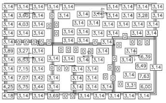
K1 Layout of structural elements – foundations
MATERIALS
Concrete: C20/25 W8 (B25)
Lean concrete: C12/15 (B15)
Reinforcing steel:
main: A-IIIN BSt500S
stirrup: A-I St3Sx-b
Concrete cover:
elements in soil 50 mm
NOTES
1. All dimensions are given in centimeters.
2. Medium silts (Mi) with Cu=20 kN/m2, corresponding to a bearing capacity
of approximately 320 kPa, were assumed as the load-bearing soil layer directly
under the foundation.
3. In case of weaker soil parameters, the foundation must be re-designed.
4. Concrete surfaces in contact with the soil should be coated with Abizol R+P.
5. A damp-proof insulation made of roofing felt should be installed on the lean
concrete, and foundation walls must be covered with waterproof insulation from
the outside.
| REPETITIVE SINGLE-FAMILY RESIDENTIAL BUILDING DM-6804 |
||
| INVESTMENT TITLE / PROJECT TITLE: |
||
| STRUCTURE | ||
| STRUCTURAL LAYOUT PLAN OF FOUNDATIONS | ||
| PREPARED BY / DESIGNED BY |
M.Sc. Eng. Krzysztof Tabaj MAP/0164/POOK/09 |
SCALE: 1:100 |
| ADAPTING DESIGNERS: |
DATE: 03.2021r. |
|
| K1 | ||
| COPYING AND DISTRIBUTION PROHIBITED! | ||
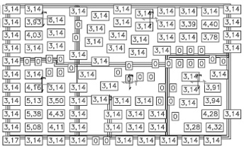
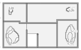
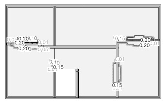
K2 Layout of structural elements – ground floor
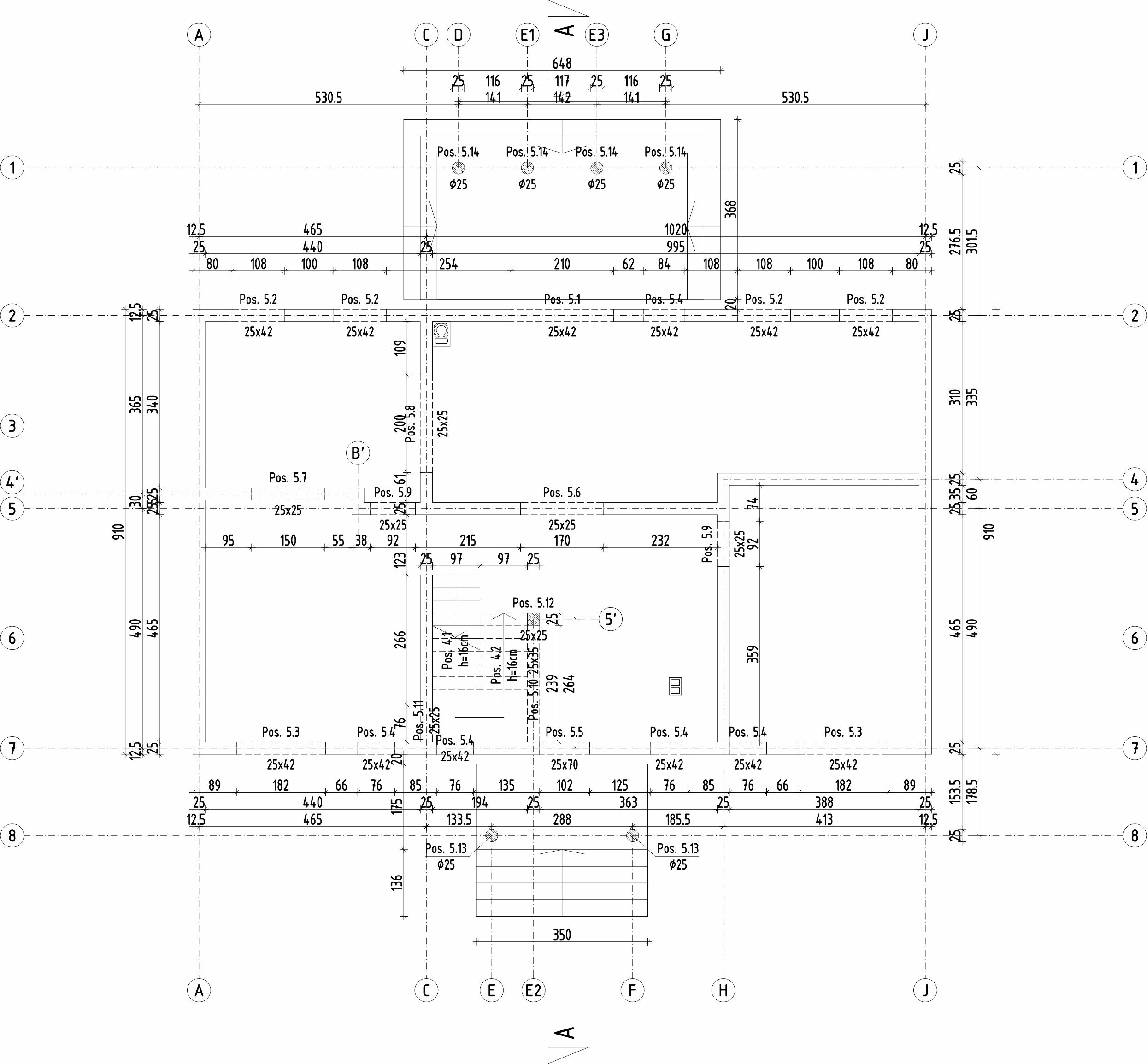
MATERIALS
Concrete: C30/37 (B37)
Lean concrete: C12/15 (B15)
Reinforcing steel: A-IIIN BSt500S
Concrete cover:
Beams 30mm
Columns 30mm
Slabs 20mm
NOTES
1. Before commencing construction, read the entire technical documentation thoroughly.
2. All construction works must be carried out under the supervision of a qualified
person in accordance with building code rules.
3. Ensure continuity of reinforcement for all reinforced concrete elements.
4. Pay close attention to the positioning of lintel levels – in accordance with
architectural drawings.
5. A 25x25 cm peripheral ring beam should be made on the walls, with local lowered
sections to the level of reinforced concrete lintels.
6. Interior partition walls should be made of 10MPa ceramic blocks.
| REPETITIVE SINGLE-FAMILY RESIDENTIAL BUILDING DM-6804 |
||
| INVESTMENT TITLE / PROJECT TITLE: |
||
| STRUCTURE | ||
| STRUCTURAL LAYOUT PLAN OF THE GROUND FLOOR | ||
| PREPARED BY / DESIGNED BY |
M.Sc. Eng. Krzysztof Tabaj MAP/0164/POOK/09 |
SCALE: 1:100 |
| ADAPTING DESIGNERS: |
DATE: 03.2021r. |
|
| K2 | ||
| COPYING AND DISTRIBUTION PROHIBITED! | ||
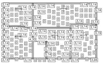
K3 Layout of structural elements – floor slab over the ground floor
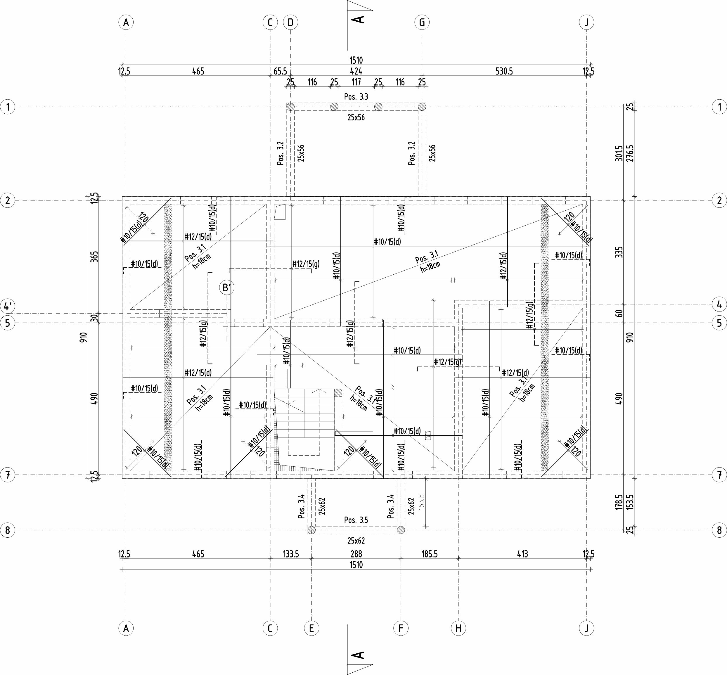
Ring beam
MATERIALS
Concrete: C30/37 (B37)
Lean concrete: C12/15 (B15)
Reinforcing steel: A-IIIN BSt500S
Concrete cover:
Beams 30mm
Columns 30mm
Slabs 20mm
NOTES
1. Before commencing construction, read the entire technical documentation thoroughly.
2. All construction works must be carried out under the supervision of a qualified
person in accordance with building code rules.
3. Ensure continuity of reinforcement for all reinforced concrete elements.
4. Pay close attention to the positioning of lintel levels – in accordance with
architectural drawings.
5. The slab must be constructed as monolithically connected to the ring beam, lintels,
and binders, based on the detailed reinforcement design and in accordance with building
code rules. Reinforcement works should be inspected and approved by the project author
or a authorized person.
6. Interior partition walls should be made of 10MPa ceramic blocks.
7. A 25x25 cm ring beam should be made on top of all walls, reinforced longitudinally
with 6#12 bars and ∅6 stirrups every 25 cm.
| REPETITIVE SINGLE-FAMILY RESIDENTIAL BUILDING DM-6804 |
||
| INVESTMENT TITLE / PROJECT TITLE: |
||
| STRUCTURE | ||
| STRUCTURAL LAYOUT PLAN OF THE CEILING ABOVE THE GROUND FLOOR |
||
| PREPARED BY / DESIGNED BY |
M.Sc. Eng. Krzysztof Tabaj MAP/0164/POOK/09 |
SCALE: 1:100 |
| ADAPTING DESIGNERS: |
DATE: 03.2021r. |
|
| K3 | ||
| COPYING AND DISTRIBUTION PROHIBITED! | ||
K4 Layout of structural elements – attic
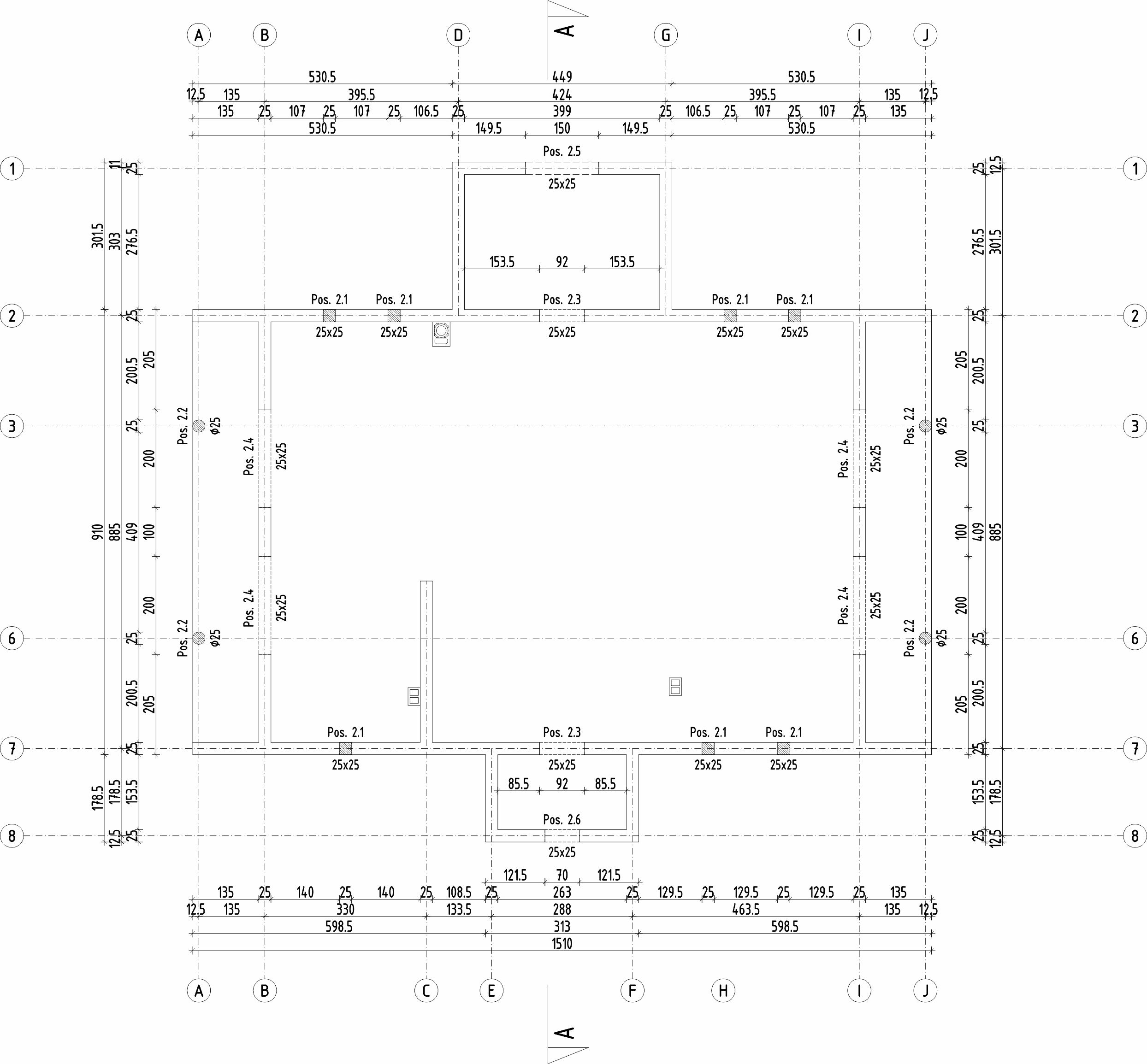
Pos. 2.7

MATERIALS
Concrete: C30/37 (B37)
Lean concrete: C12/15 (B15)
Reinforcing steel: A-IIIN BSt500S
Concrete cover:
Beams 30mm
Columns 30mm
Slabs 20mm
NOTES
1. Before commencing construction, read the entire technical documentation thoroughly.
2. All construction works must be carried out under the supervision of a qualified person
in accordance with building code rules.
3. Ensure continuity of reinforcement for all reinforced concrete elements.
4. Pay close attention to the positioning of lintel levels – in accordance with architectural
drawings.
5. The slab must be constructed as monolithically connected to the ring beam, lintels,
and binders, based on the detailed reinforcement design and in accordance with building
code rules.
6. Reinforcement works should be inspected and approved by the project author or a qualified
person.
7. Partition walls should be made of grade 400 cellular concrete blocks.
8. A 25x25 cm ring beam should be made on top of all load-bearing walls, reinforced
longitudinally with 6#12 bars and ∅6 stirrups every 25 cm.
| REPETITIVE SINGLE-FAMILY RESIDENTIAL BUILDING DM-6804 |
||
| INVESTMENT TITLE / PROJECT TITLE: |
||
| STRUCTURE | ||
| ATTIC STRUCTURAL LAYOUT PLAN | ||
| PREPARED BY / DESIGNED BY |
M.Sc. Eng. Krzysztof Tabaj MAP/0164/POOK/09 |
SCALE: 1:100 |
| ADAPTING DESIGNERS: |
DATE: 03.2021r. |
|
| K4 | ||
| COPYING AND DISTRIBUTION PROHIBITED! | ||
K5 Layout of structural elements – roof
MATERIALS
Concrete: C20/25 (B25)
Reinforcing steel:
main: A-IIIN BSt500S
stirrups: A-I St3SX
Wood C24
NOTES
1. Before commencing construction, read the entire technical documentation thoroughly.
2. All construction works must be carried out under the supervision of a qualified
person in accordance with building code rules.
3. The wall plates should be anchored to the ring beam of the queen post walls with
∅16 anchors, spaced no more than every 1.5m.
4. Timber elements must be protected with biological and fire protection agents, e.g., INTIOX-S.
5. The roof structure should be additionally stiffened in the upper plane of the collar beams
by nailing 22mm OSB-3 boards. The use of perforated steel strapping tapes in the upper plane
of the rafters is additionally recommended.
6. The rafter notches for the wall plates and purlins should be 3cm.
| REPETITIVE SINGLE-FAMILY RESIDENTIAL BUILDING DM-6804 |
||
| INVESTMENT TITLE / PROJECT TITLE: |
||
| STRUCTURE | ||
| ROOF STRUCTURAL LAYOUT PLAN | ||
| PREPARED BY / DESIGNED BY |
M.Sc. Eng. Krzysztof Tabaj MAP/0164/POOK/09 |
SCALE: 1:100 |
| ADAPTING DESIGNERS: |
DATE: 03.2021r. |
|
| K5 | ||
| COPYING AND DISTRIBUTION PROHIBITED! | ||
K6 Characteristic sections
MATERIALS
Concrete: C30/37(B37)
Lean concrete: C12/15 (B15)
Reinforcing steel: A-IIIN BSt500S
Concrete cover:
beams 30mm
columns 30mm
slabs 20mm
elements in soil 50mm
Wood C24
NOTES
1. All dimensions are given in centimeters.
2. Medium silts (Mll) with qf=20kN/m2, which corresponds to a subgrade modulus
of 320kPa, were assumed as the soil layer directly under the foundation.
3. In case of different soil parameters, the foundation should be re-designed.
4. Concrete surfaces in contact with soil should be protected with R+P asphalt emulsion.
5. Horizontal damp-proof insulation made of roofing felt should be installed on the lean
concrete, and foundation walls should be separated from the outside with heat-weldable
roofing felt.
6. Before commencing construction, read the entire technical documentation thoroughly.
7. All construction works must be carried out under the supervision of a qualified person
in accordance with building code rules.
8. Ensure continuity of reinforcement for reinforced concrete elements.
9. Pay close attention to the positioning of lintel supports – in accordance with
architectural drawings.
10. A 25x25cm peripheral ring beam should be made on the walls, with local lowered sections
to the level of lintel supports.
11. Partition walls in the ground floor should be made of 10MPa ceramic blocks. Partition
walls in the attic should be made of grade 400 cellular concrete blocks.
12. The anchors for the wall plate should be made of ø14 steel rods, spaced no more
than every 1.5m.
13. Timber elements must be protected with biological and fire protection
agents, e.g., UNIOX-B.
14. The roof structure should be additionally stiffened in the top plane of the beams
by nailing 22mm OSB-3 boards. The use of perforated steel tapes is additionally
recommended to stiffen the roof plane.
15. Anchoring of the ridge beam under the 5cm thick ridge purlin.
| REPETITIVE SINGLE-FAMILY RESIDENTIAL BUILDING DM-6804 |
||
| INVESTMENT TITLE / PROJECT TITLE: |
||
| STRUCTURE | ||
| CROSS-SECTION A-A | ||
| PREPARED BY / DESIGNED BY |
M.Sc. Eng. Krzysztof Tabaj MAP/0164/POOK/09 |
SCALE: 1:100 |
| ADAPTING DESIGNERS: |
DATE: 03.2021r. |
|
| K6 | ||
| COPYING AND DISTRIBUTION PROHIBITED! | ||
K7 Reinforcement of reinforced concrete elements
Pos. 6.1
Pos. 6.2
Pos. 6.3
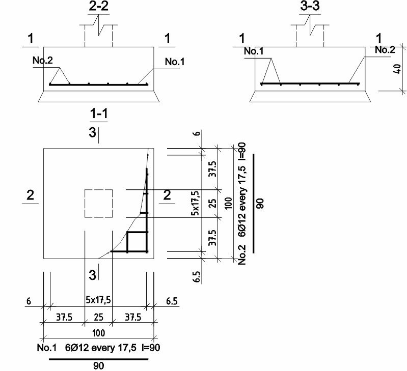
Pos. 6.4, 6.5
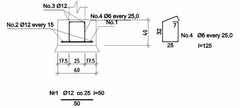
Pos. 6.6
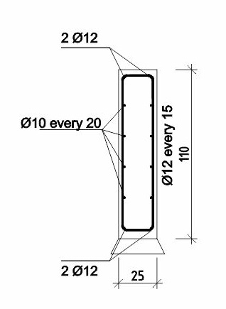
Pos. 6.7
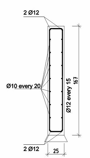
Pos. 6.8
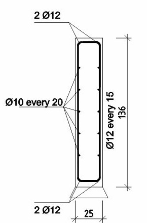
MATERIALS
Concrete: C20/25(B25)
Steel: BSt500S
Concrete cover: Cnom=50mm
| REPETITIVE SINGLE-FAMILY RESIDENTIAL BUILDING DM-6804 |
||
| INVESTMENT TITLE / PROJECT TITLE: |
||
| STRUCTURE | ||
| STRUCTURAL DETAILS | ||
| PREPARED BY / DESIGNED BY |
M.Sc. Eng. Krzysztof Tabaj MAP/0164/POOK/09 |
SCALE: 1:25 |
| ADAPTING DESIGNERS: |
DATE: 03.2021r. |
|
| K7 | ||
| COPYING AND DISTRIBUTION PROHIBITED! | ||
K8 Reinforcement of reinforced concrete elements
Pos. 5.1

Pos. 5.2
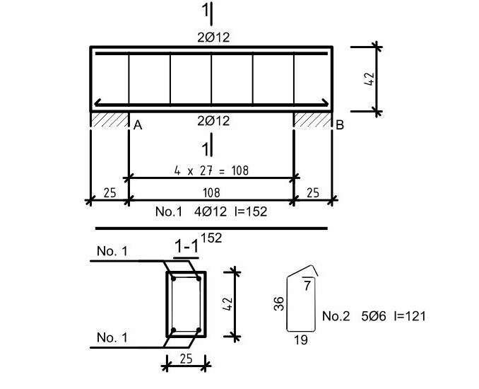
Pos. 5.3
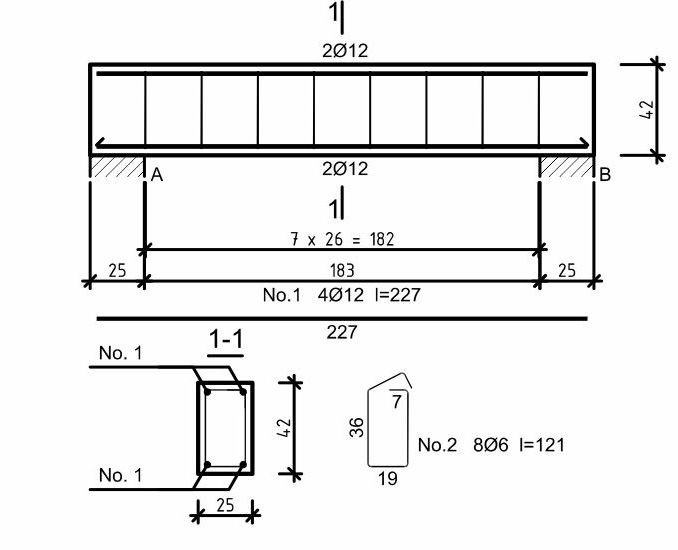
Pos. 5.4

Pos. 5.5
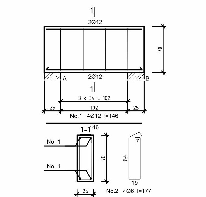
Pos. 5.6
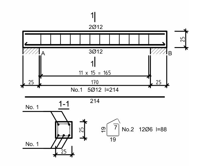
MATERIALS
Concrete: C20/25(B25)
Steel: BSt500S
Concrete cover: Cnom=30mm
| REPETITIVE SINGLE-FAMILY RESIDENTIAL BUILDING DM-6804 |
||
| INVESTMENT TITLE / PROJECT TITLE: |
||
| STRUCTURE | ||
| STRUCTURAL DETAILS | ||
| PREPARED BY / DESIGNED BY |
M.Sc. Eng. Krzysztof Tabaj MAP/0164/POOK/09 |
SCALE: 1:25 |
| ADAPTING DESIGNERS: |
DATE: 03.2021r. |
|
| K8 | ||
| COPYING AND DISTRIBUTION PROHIBITED! | ||
K9 Reinforcement of reinforced concrete elements
Pos. 5.7
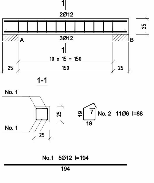
Pos. 5.8
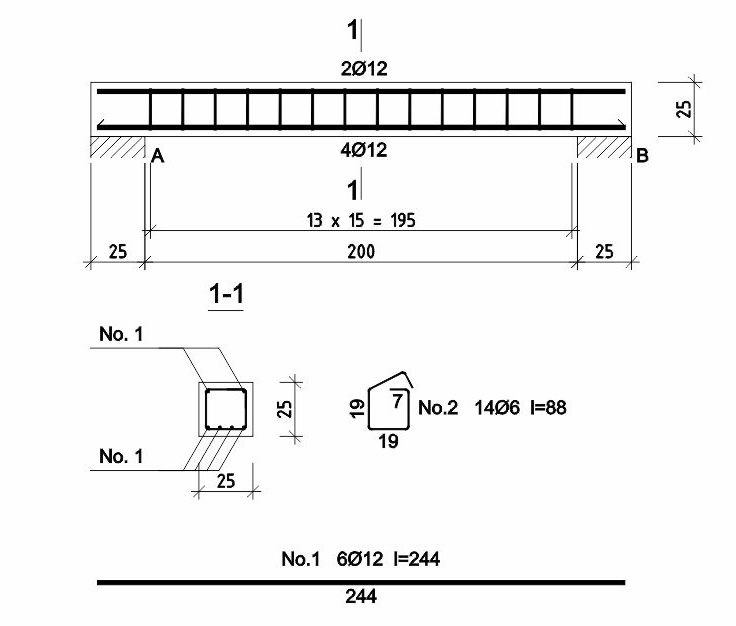
Pos. 5.9
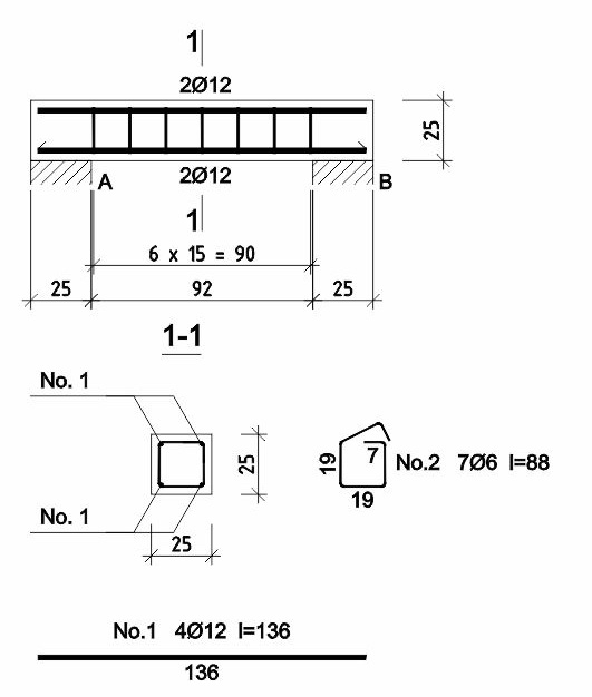
Pos. 5.10
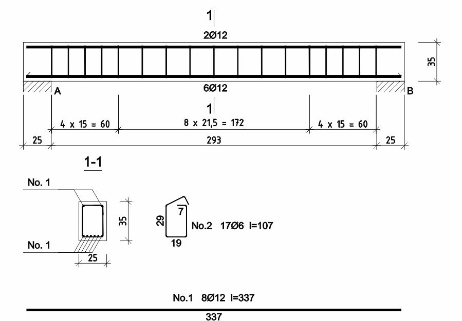
Pos. 5.11
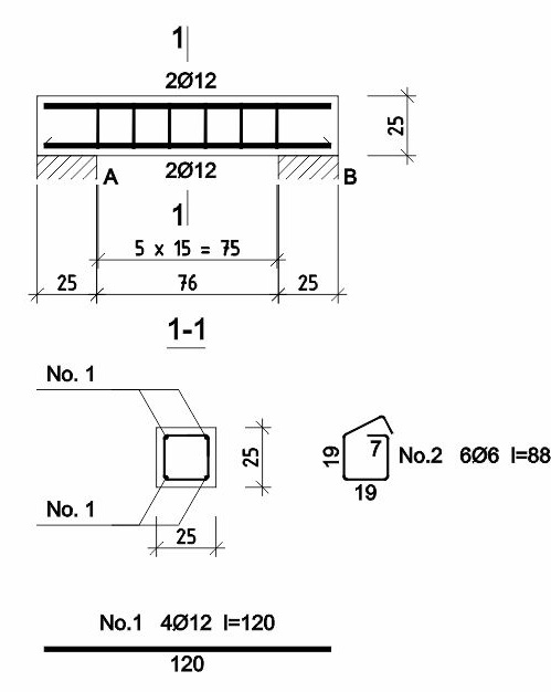
MATERIALS
Concrete: C20/25(B25)
Steel: BSt500S
Concrete cover: Cnom=30mm
| REPETITIVE SINGLE-FAMILY RESIDENTIAL BUILDING DM-6804 |
||
| INVESTMENT TITLE / PROJECT TITLE: |
||
| STRUCTURE | ||
| STRUCTURAL DETAILS | ||
| PREPARED BY / DESIGNED BY |
M.Sc. Eng. Krzysztof Tabaj MAP/0164/POOK/09 |
SCALE: 1:25 |
| ADAPTING DESIGNERS: |
DATE: 03.2021r. |
|
| K9 | ||
| COPYING AND DISTRIBUTION PROHIBITED! | ||
K10 Reinforcement of reinforced concrete elements
Pos. 5.12
Make 1 piece
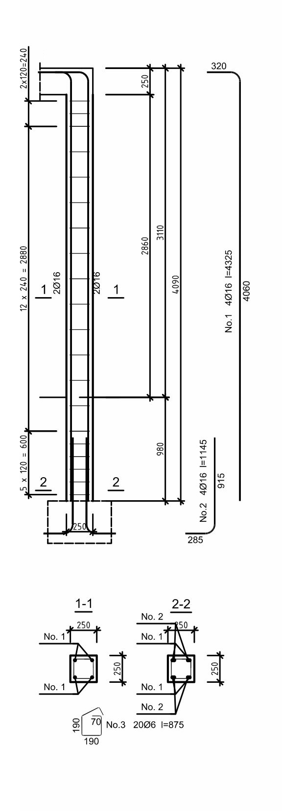
Pos. 5.13
Make 2 pieces
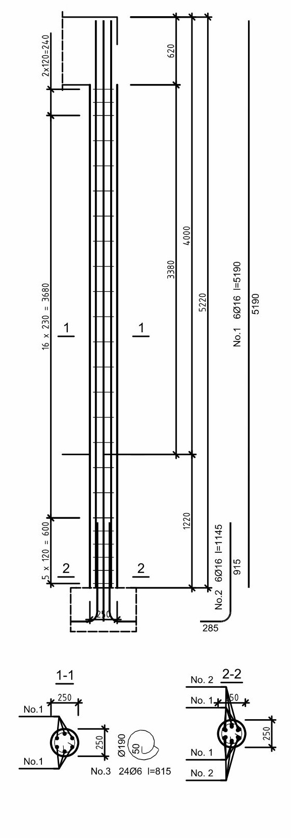
Pos. 5.14
Make 4 pieces
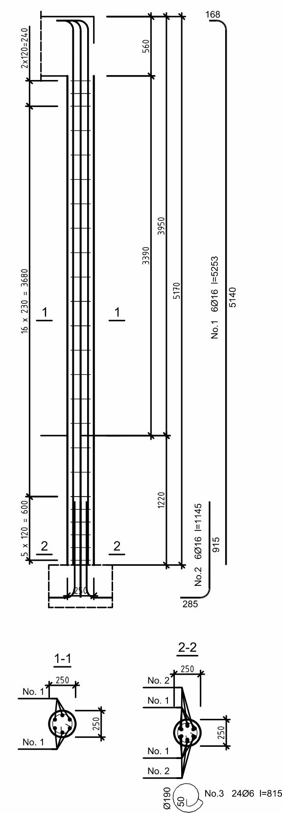
MATERIALS
Concrete: C20/25(B25)
Steel: BSt500S
Concrete cover: Cnom=30mm
| REPETITIVE SINGLE-FAMILY RESIDENTIAL BUILDING DM-6804 |
||
| INVESTMENT TITLE / PROJECT TITLE: |
||
| STRUCTURE | ||
| STRUCTURAL DETAILS | ||
| PREPARED BY / DESIGNED BY |
M.Sc. Eng. Krzysztof Tabaj MAP/0164/POOK/09 |
SCALE: 1:25 |
| ADAPTING DESIGNERS: |
DATE: 03.2021r. |
|
| K10 | ||
| COPYING AND DISTRIBUTION PROHIBITED! | ||
K11 Reinforcement of reinforced concrete elements
Pos. 4.2
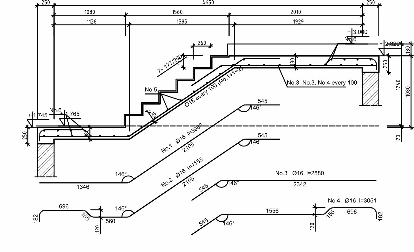
Pos. 4.1
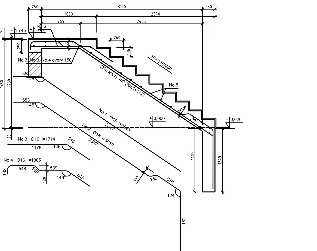
MATERIALS
Concrete: C20/25(B25)
Steel: BSt500S
Concrete cover: Cnom=20mm
| REPETITIVE SINGLE-FAMILY RESIDENTIAL BUILDING DM-6804 |
||
| INVESTMENT TITLE / PROJECT TITLE: |
||
| STRUCTURE | ||
| STRUCTURAL DETAILS | ||
| PREPARED BY / DESIGNED BY |
M.Sc. Eng. Krzysztof Tabaj MAP/0164/POOK/09 |
SCALE: 1:25 |
| ADAPTING DESIGNERS: |
DATE: 03.2021r. |
|
| K11 | ||
| COPYING AND DISTRIBUTION PROHIBITED! | ||
K12 Reinforcement of reinforced concrete elements
Pos. 3.2
Make 2 pieces
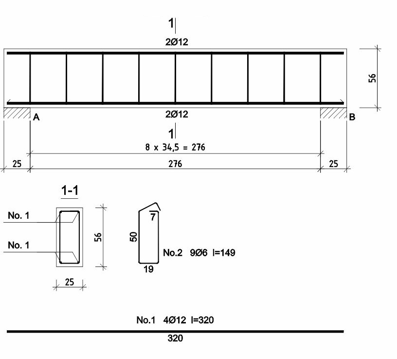
Pos. 3.3
Make 1 piece
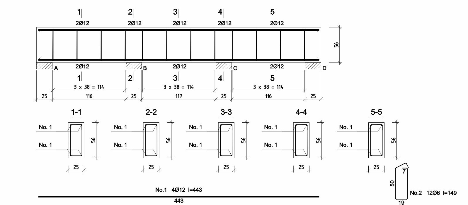
Pos. 3.4
Make 2 pieces

Pos. 3.5
Make 1 piece
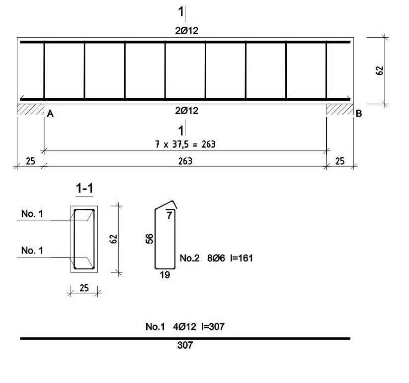
MATERIALS
Concrete: C20/25(B25)
Steel: BSt500S
Concrete cover: Cnom=30mm
| REPETITIVE SINGLE-FAMILY RESIDENTIAL BUILDING DM-6804 |
||
| INVESTMENT TITLE / PROJECT TITLE: |
||
| STRUCTURE | ||
| STRUCTURAL DETAILS | ||
| PREPARED BY / DESIGNED BY |
M.Sc. Eng. Krzysztof Tabaj MAP/0164/POOK/09 |
SCALE: 1:25 |
| ADAPTING DESIGNERS: |
DATE: 03.2021r. |
|
| K12 | ||
| COPYING AND DISTRIBUTION PROHIBITED! | ||
K13 Reinforcement of reinforced concrete elements
Pos. 2.1
Make 7 pieces
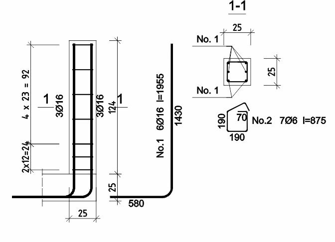
Pos. 2.2
Make 4 pieces

Pos. 2.3
Make 2 pieces
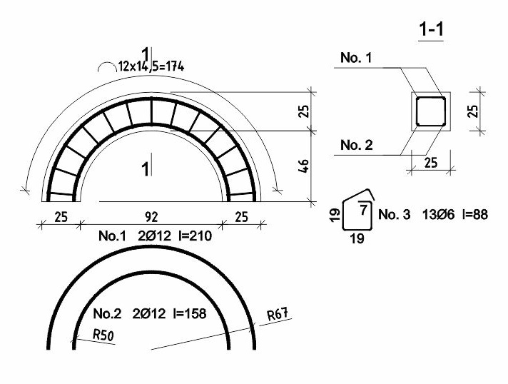
Pos. 2.4
Make 4 pieces
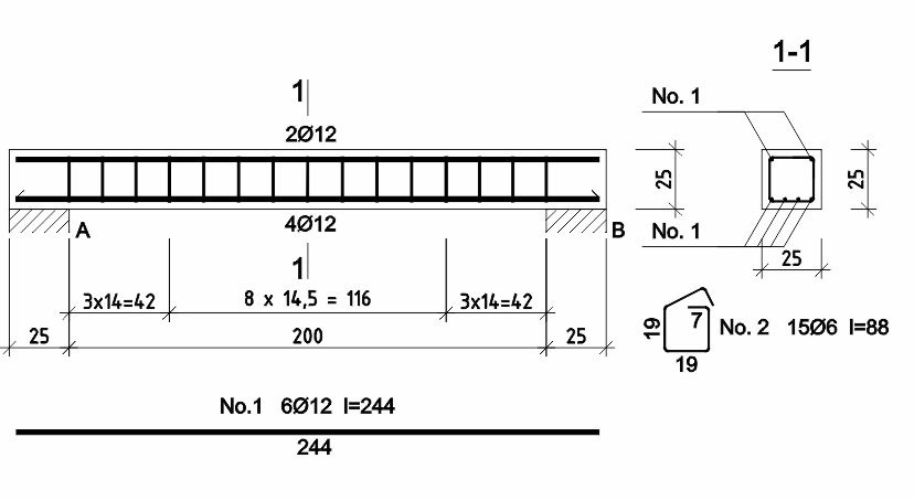
Pos. 2.5
Make 1 piece
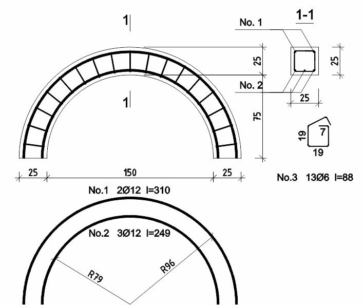
Pos. 2.6
Make 1 piece
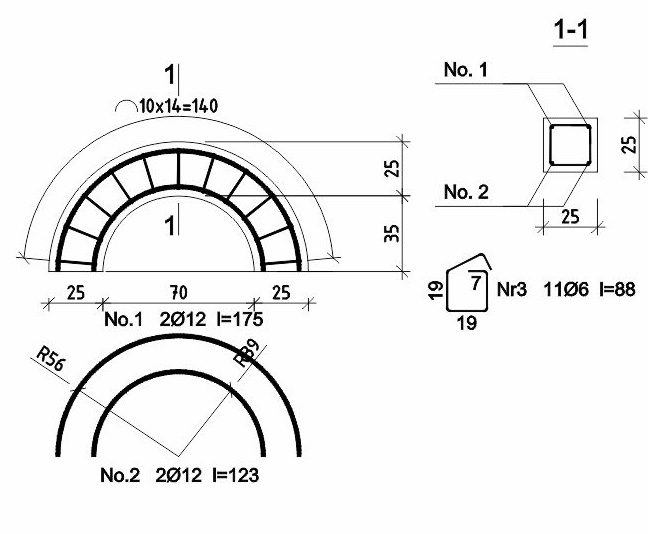
MATERIALS
Concrete: C20/25(B25)
Steel: BSt500S
Concrete cover: Cnom=30mm
| REPETITIVE SINGLE-FAMILY RESIDENTIAL BUILDING DM-6804 |
||
| INVESTMENT TITLE / PROJECT TITLE: |
||
| STRUCTURE | ||
| STRUCTURAL DETAILS | ||
| PREPARED BY / DESIGNED BY |
M.Sc. Eng. Krzysztof Tabaj MAP/0164/POOK/09 |
SCALE: 1:25 |
| ADAPTING DESIGNERS: |
DATE: 03.2021r. |
|
| K13 | ||
| COPYING AND DISTRIBUTION PROHIBITED! | ||
Technical design of internal water and sewage systems and internal central heating system with a heat pump
For the repetitive architectural and construction project of a single-family residential building DM-6804
Internal water and sewage system.
1. General data
- Single-family building without a basement
- Before proceeding with the installation of the internal system and the connection, technical conditions must be obtained from the local water supplier
- Average daily water consumption: Q = 0.65 m³/day
- Water supply is planned from the municipal water supply network or from a private intake via a pressure tank set (hydrophore)
- The water connection should be made using a Dn 32 galvanized steel pipe insulated with Denso tape, or alternatively, a PE Dn 40×4.2 polyethylene pipe
- Minimum pipe laying depth: 1.7 m. Pipes should be laid on a sand bedding
- Water consumption measurement is planned in the utility room using a Dn 20 mm vane‑wheel water meter
2. Internal installation
- The internal hot and cold water installation is planned to be executed using WIRSBRO technology with Wirsbro‑PEX polyethylene pipes in a tee system
- This involves routing pipes under the floor with branches connected via tees
- Only within the vicinity of the boiler and the water heater should the installations be made using copper pipes
- All pipes routed under the floor and in wall chases must be placed in Peschl protective tubing (conduit)
- Hot water will be prepared by a Samsung ClimateHubSplit heat pump with a thermal power of 12.0 kW
- The pump features a built‑in domestic hot water (DHW) heater with a capacity of 200 l, with Ne = 3.0 kW and U = 230 V
3. Sewage installation
- Sewage from the building can be discharged into the municipal sewage system or, alternatively, into a holding tank (septic tank)
- The sanitary sewage connection should be made of PVC 160 pipes on a sand bedding below the ground frost line, i.e., 120 cm
- The internal sewage system is to be made of PVC pipes and fittings, with the sewage stack ending in a roof vent
- Cleanouts (access eyes) should be installed at the base of the stacks
- Horizontal lines should be laid with a slope of 2–3%
4. Final remarks
- Hot and cold water installation works must be carried out in accordance with the requirements of WIRSBRO technology (sanitary installation manual)
- Other assembly and acceptance works must be performed in accordance with the "Technical Conditions for the Execution and Acceptance of Construction and Assembly Works," Part II: "Sanitary and Industrial Installation Works"
S1 Ground floor plan – water and sewage installation
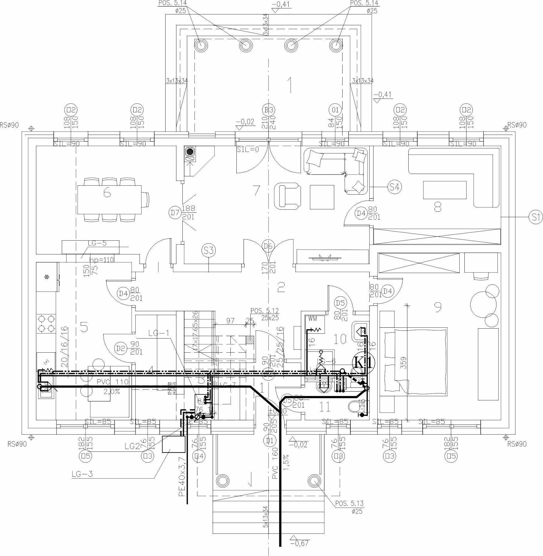
LEGEND
 |
proposed cold water |
 |
proposed circulation |
 |
proposed hot water |
 |
proposed sewage |
KEY
LG-1 - heat pump
LG-2 - water meter JS2,5 dn20
LG-3 - outdoor unit for heat pump
LG-4 - roof step
LG-5 - semi-circular opening 150x75
LG-6 - window sill height 2,1m
LG-7 - built-in wardrobe
| REPETITIVE SINGLE-FAMILY RESIDENTIAL BUILDING DM-6804 |
||
| INVESTMENT TITLE / PROJECT TITLE: |
||
| SANITARY | ||
| GROUND FLOOR PLAN – WATER AND SEWAGE INSTALLATION | ||
| PREPARED BY / DESIGNED BY |
B.Eng. MAREK TARADA BPP. 8388-289/79 |
DATE: 03.2021r. |
| APPROVED BY: | SCALE: 1:100 |
|
| ADAPTING DESIGNER: |
S1 | |
| COPYING AND DISTRIBUTION PROHIBITED! | ||
S2 Attic plan – water and sewage installation
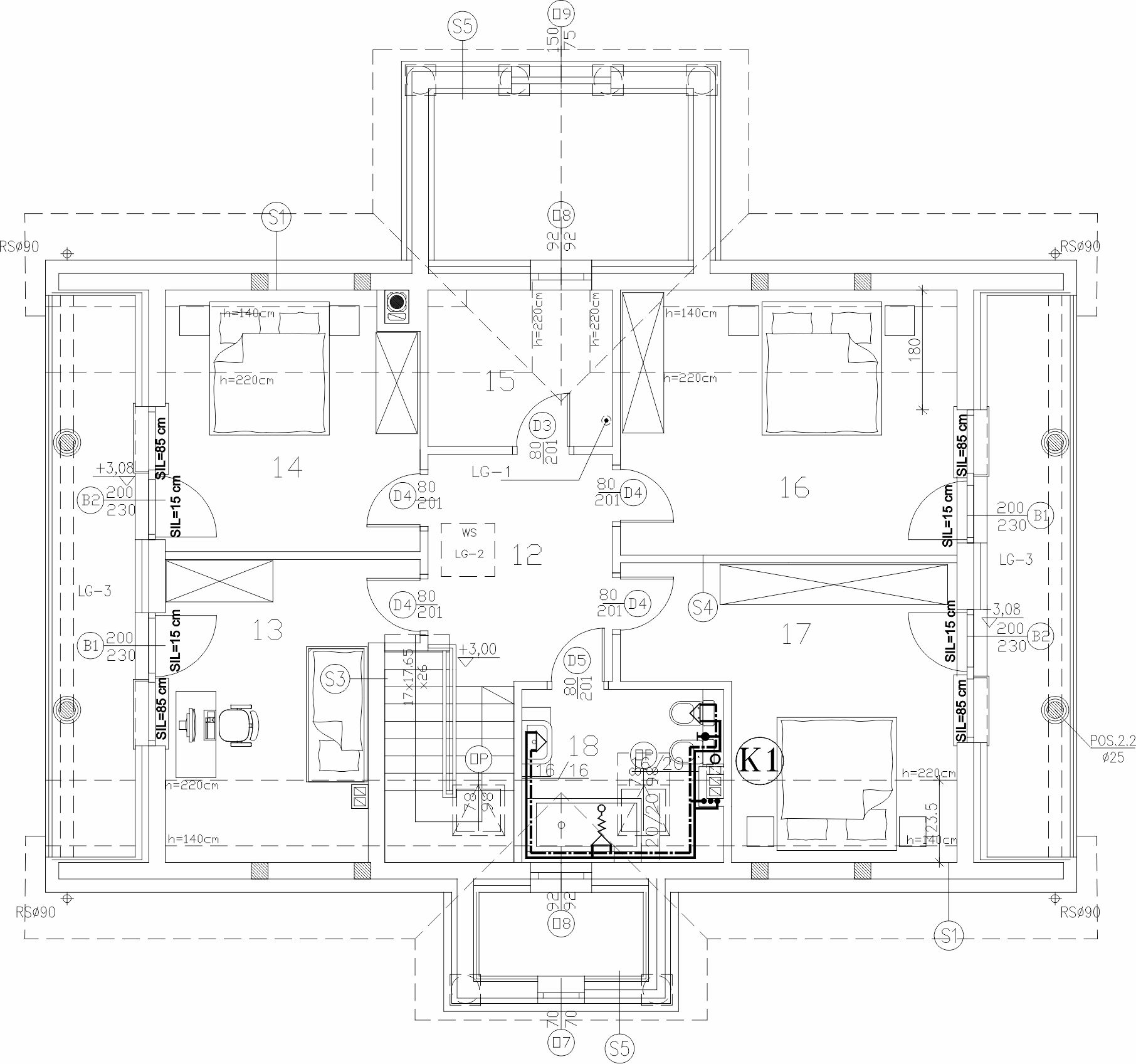
LEGEND
|
proposed cold water |
|
proposed circulation |
|
proposed hot water |
|
proposed sewage |
KEY
LG-1 - ceiling vent
LG-2 - attic access
LG-3 - loggia
| REPETITIVE SINGLE-FAMILY RESIDENTIAL BUILDING DM-6804 |
||
| INVESTMENT TITLE / PROJECT TITLE: |
||
| SANITARY | ||
| ATTIC PLAN – WATER AND SEWAGE INSTALLATION | ||
| PREPARED BY / DESIGNED BY |
B.Eng. MAREK TARADA BPP. 8388-289/79 |
DATE: 03.2021r. |
| APPROVED BY: | SCALE: 1:100 |
|
| ADAPTING DESIGNER: |
S2 | |
| COPYING AND DISTRIBUTION PROHIBITED! | ||
Internal central heating installation.
1. General data
- Semi-detached single-family building without a basement
- The building will be heated from its own heat source — a Samsung ClimateHub Split heat pump with a power of 12.0 kW
- Design parameters for heating water:
- Tv = 50°C (Supply temperature)
- Tr = 30°C (Return temperature)
- Ti = 20°C (Indoor design temperature)
- Heat demand for central heating: Q = 11,575 W
2. Underfloor heating
- Supply for underfloor heating loops is provided from distributor cabinets with pump mixing, connected directly to the heat pump
- Loops must be laid according to the manufacturer's guidelines
3. Installation
- The system is designed using WIRSBRO technology with Wirsbro‑evalPex polyethylene pipes
- Pipes are to be routed in the floor on polystyrene insulation within Peschl protective tubing
- Minimum screed thickness over the pipe insulation: 3.5 cm
- Heat pump connections must be made of copper pipes for a section of at least 1.5 m, encased in polyurethane foam insulation
- The system should be filled with tap water or non‑freezing liquid
4. Pressure tests
- Leakage tests must be performed cold and hot in accordance with the pipe manufacturer's recommendations and technical conditions for installation acceptance
5. Final remarks
- Supply and exhaust ventilation and a flue gas duct must be installed in the boiler room
- Installation, assembly, and acceptance works must comply with "Technical Conditions for the Execution and Acceptance of Construction and Assembly Works," Part II: "Sanitary and Industrial Installation Works"
S3 Ground floor plan – central heating
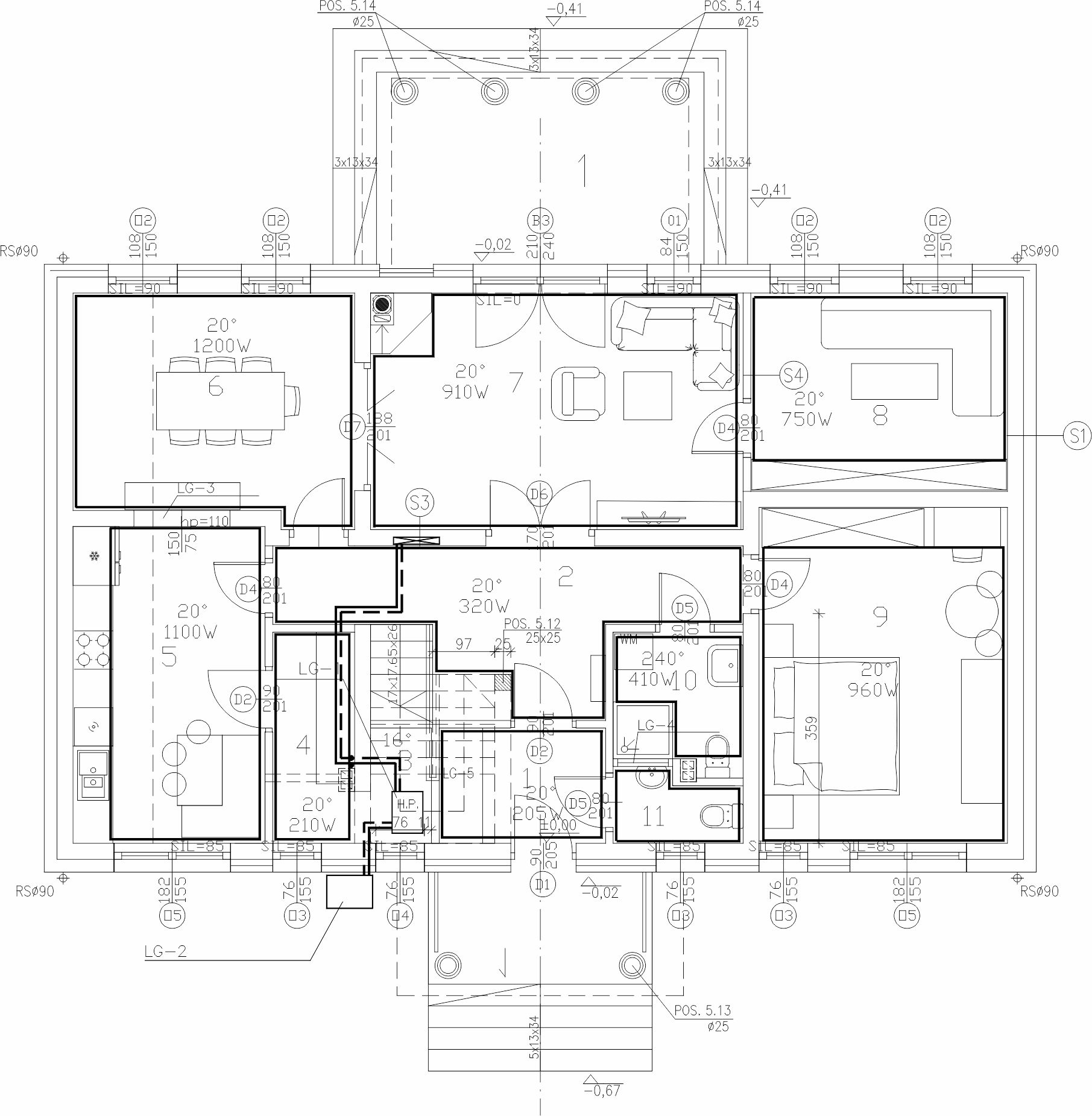
LEGEND
 |
central heating pipes in floor layers |
 |
manifold cabinet for underfloor heating |
 |
underfloor heating loop (UFH loop) |
KEY
LG-1 - heat pump
LG-2 - outdoor unit for heat pump
LG-3 - semi-circular opening 150x75
LG-4 - window sill height 2,1m
LG-5 - built-in wardrobe
| REPETITIVE SINGLE-FAMILY RESIDENTIAL BUILDING DM-6804 |
||
| INVESTMENT TITLE / PROJECT TITLE: |
||
| SANITARY | ||
| GROUND FLOOR PLAN – CENTRAL HEATING | ||
| PREPARED BY / DESIGNED BY |
B.Eng. MAREK TARADA BPP. 8388-289/79 |
DATE: 03.2021r. |
| APPROVED BY: | SCALE: 1:100 |
|
| ADAPTING DESIGNER: |
S3 | |
| COPYING AND DISTRIBUTION PROHIBITED! | ||
S4 Attic plan – central heating
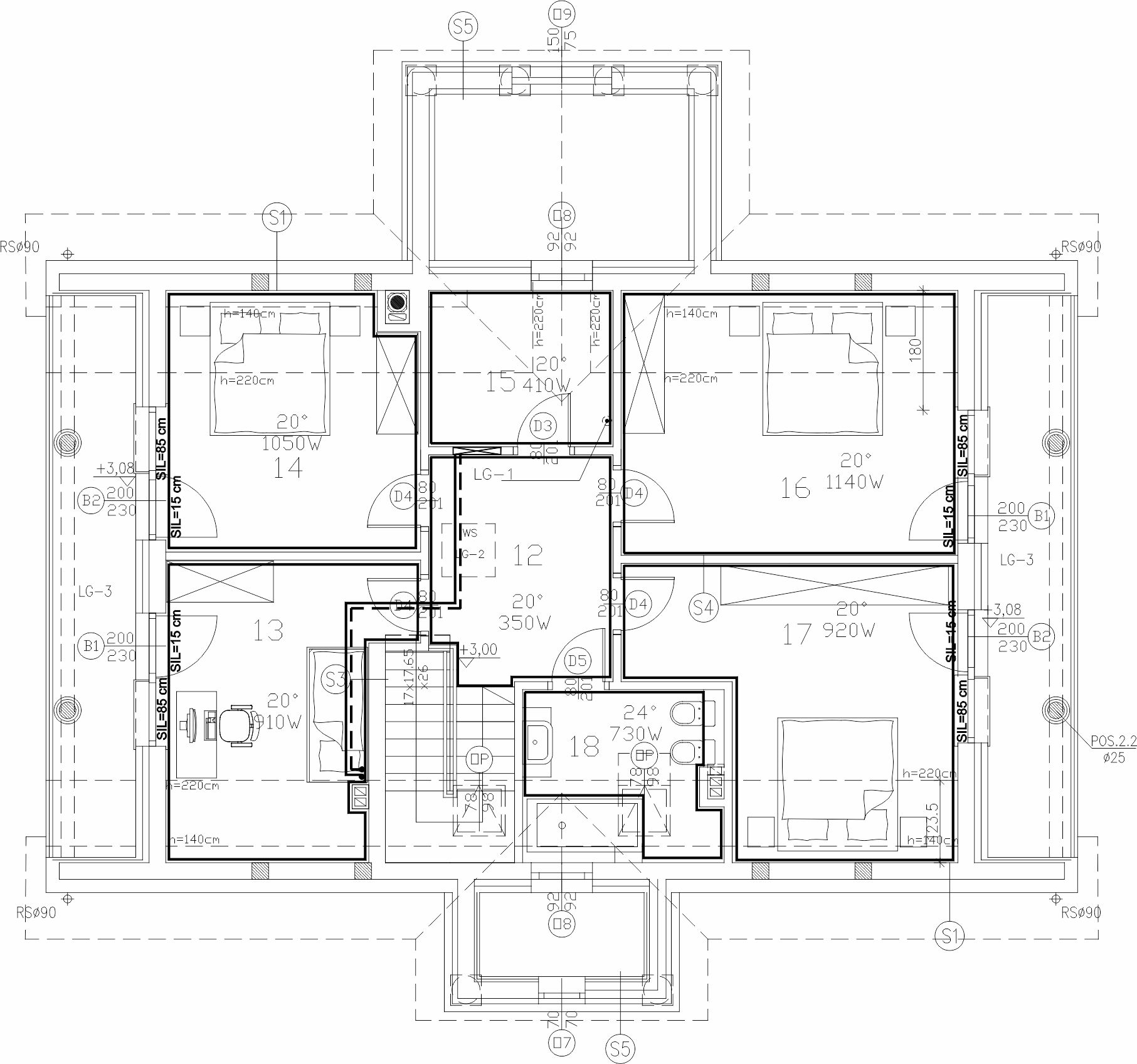
LEGEND
|
central heating pipes in floor layers |
|
manifold cabinet for underfloor heating |
|
underfloor heating loop (UFH loop) |
KEY
LG-1 - ceiling vent
LG-2 - attic access
LG-3 - loggia
| REPETITIVE SINGLE-FAMILY RESIDENTIAL BUILDING DM-6804 |
||
| INVESTMENT TITLE / PROJECT TITLE: |
||
| SANITARY | ||
| ATTIC PLAN – CENTRAL HEATING | ||
| PREPARED BY / DESIGNED BY |
B.Eng. MAREK TARADA BPP. 8388-289/79 |
DATE: 03.2021r. |
| APPROVED BY: | SCALE: 1:100 |
|
| ADAPTING DESIGNER: |
S4 | |
| COPYING AND DISTRIBUTION PROHIBITED! | ||
S5 Water and sewage schematic diagram
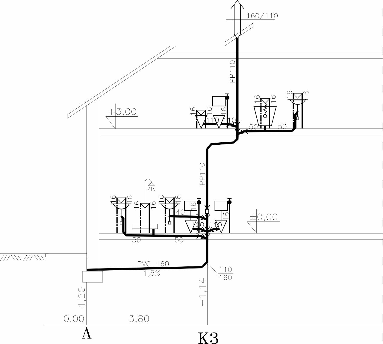
| REPETITIVE SINGLE-FAMILY RESIDENTIAL BUILDING DM-6804 |
||
| INVESTMENT TITLE / PROJECT TITLE: |
||
| SANITARY | ||
| WATER AND SEWAGE SCHEMATIC DIAGRAM | ||
| PREPARED BY / DESIGNED BY |
B.Eng. MAREK TARADA BPP. 8388-289/79 |
DATE: 03.2021r. |
| APPROVED BY: | SCALE: 1:100 |
|
| ADAPTING DESIGNER: |
S5 | |
| COPYING AND DISTRIBUTION PROHIBITED! | ||
Technical description – electrical branch
The subject of this study is the electrical and lightning protection installation for a repeatable residential building, model DM-6804.
Table of contents
1. General data
2. Basis of the design
3. Scope of the design
4. Connection to the power grid
5. Internal electrical installation
5.1 0.4kV low voltage cable line
5.2 Main distribution board (MDB) "R"
5.3 Sockets and outlets circuits
5.4 General lighting circuits
5.5 Electric shock protection system
5.6 Overvoltage protection system (surge protection)
5.7 Lightning protection system
6. Photovoltaic (PV) installation
6.1. System schematic diagram
7. Final Remarks
E1 - Diagram of the distribution board "R"
E2 - Photovoltaic system schematic diagram
E3 - Ground floor plan
E4 - Attic plan
E5 - Roof plan
1. General data
- Electrical Equipment Construction Regulations, 4th edition (1996) with subsequent amendments
- PN‑IEC 60364 – Electrical installations in buildings
- N SEP‑E‑001 – Low-voltage power networks: Protection against electric shock
- N SEP‑E‑002 – Electrical installations in buildings
- PN‑EN 62305 – Lightning protection
- Construction Law Act of July 7, 1994 (consolidated text, Journal of Laws of 2013, item 1409)
- Other current regulations and standards covering the subject of this study
2. Basis of design
The documentation has been developed based on:
- Architectural layouts (base maps)
- Applicable standards and regulations
- Investor guidelines
3. Scope of design
As part of this study, the following installations have been designed:
- Equipotential bonding
- General-purpose socket outlets
- General lighting
- Electric shock protection
- Surge protection
- Lightning protection and earthing system
4. Connection to the power grid
The designed building will be supplied from a Metering and Connection Set (ZZP), in accordance with the connection conditions issued by the Power Company. The cable connection is outside the scope of this study.
Supply parameters:
- Ps = 14 kW – building peak power
- U = 230/400 V
- f = 50 Hz
- Is = 25 A – post‑meter protection value
5. Internal electrical installation
The subject of this study is the electrical and lightning protection installation for a repeatable residential building, model DM-6804.
The building is to be equipped with Distribution Board R. Distribution Board R shall be supplied from the Metering and Connection Set (ZZP), in accordance with the connection conditions issued by the Power Company. The ZZP is the subject of a separate study.
All electrical loads in the building must be supplied from Distribution Board R.
The internal electrical installation plan is presented in drawings E3, E4, and E5. The building layouts show the locations of socket outlets, light points and switches, equipotential bonding, the electrical distribution board, and the lightning protection system.
Every circuit originating from the electrical distribution board is protected by appropriate switchgear and 30mA residual current devices (RCDs). The schematic for distribution board R is shown in drawing No. E1. The electrical installation must be carried out using the following cables:
Lighting circuits: YDYp 3(4)x1.5mm² cables.
Single-phase (1-f) socket supply circuits: YDYp 3x2.5mm² cables.
Three-phase (3-f) socket supply circuits: five-core YDYp cables with cross-sections adapted to the load.
The entire installation must be performed in accordance with the PBUE regulations, PN-IEC 60364, and N SEP-E-002.
5.1 0.4kV low voltage cable line
The building's distribution board will be supplied by a 0.4kV low-voltage (LV) cable line from the Metering and Connection Set (ZZP), in accordance with the connection conditions issued by the Power Company. The Metering and Connection Set is outside the scope of this study.
The designed 0.4kV low-voltage cable line (internal supply line) must be routed in the ground at a minimum depth of 0.7m. This is to be done after preparing at least 10 cm of sand bedding. Subsequently, the cable must be covered with a layer of sand. On top of the sand, a layer of native soil should be placed and covered with blue cable warning tape. At intersections with other utilities, the designed cable line must be laid in protective conduit pipes along the entire length of the intersection and an additional 0.5m on each side.
The designed cable line must be equipped with permanent cable markers along its entire length. The content of the description on the markers must be agreed upon with the owner of the line. The points where the cable enters the surrounding conduits should be sealed, and the cable must be protected against damage. The designed 0.4kV LV cable line should be introduced into the building through a designed cable duct (penetration).
5.2 Distribution board R
Distribution Board R performs the function of distributing electrical energy to all circuits in the building. Distribution Board R shall be equipped with a main disconnector, class I+II surge arresters, voltage control, overcurrent circuit breakers, and 30mA residual current devices.
Distribution Board R will be installed in the vestibule, in accordance with drawing no. E3. Distribution Board R is to be supplied from the metering and connection set.
Distribution Board R in a recessed or surface-mounted enclosure, minimum IP30 rating, insulation class II. The electrical schematic of Distribution Board R is presented in drawing E1.
5.3 Socket and outlet circuits
- Single-phase (1‑f) socket circuits: These must be installed using YDY(p) 3×2.5 mm² cables
- Three-phase (3‑f) circuits: These must use five‑core cables with cross‑sections specified in the schematic
- Installation method: Cables are to be installed flush‑mounted (under‑plaster)
- Plaster coverage: Cables routed on walls must be covered by at least 5 mm of plaster
- Tiled areas: Under wall tiles (glazing), cables must be routed in installation conduits
- Cable allowance: At least 1 m of spare cable/wire must be left for cable outlets
- Placement: The locations of sockets and cable outlets are shown in drawings E3 and E4
- Routing: Supply cable routes must run in straight lines; diagonal routing is not permitted
- Clearances: Distances from windows, doors, ceilings, floors, and socket mounting heights must comply with PBUE, PN‑IEC 60364, and N SEP‑E‑002 regulations
5.4 General lighting circuits
- Wiring: Lighting circuits must be installed using YDY(p) 3(4)×1.5 mm² cables
- Installation Method: Cables are to be routed flush‑mounted (under‑plaster)
- Plaster Coverage: Cables routed on walls must be covered by at least a 5 mm layer of plaster
- Tiled Areas: Under wall tiles, cables must be routed in installation conduits
- Cable Allowance: At least 1 m of spare cable must be left for lighting outlets
- Placement: The locations of lighting outlets for individual circuits are shown in drawings E3 and E4
- Routing: Supply cable routes must run in straight lines; diagonal routing is not permitted
- Clearances: Distances from windows, doors, ceilings, and floors, as well as switch mounting locations, must comply with PBUE, PN‑IEC 60364, and N SEP‑E‑002 regulations
- Control: Lighting control is to be implemented using single‑pole, two‑circuit (chandelier), three‑way (stair), and four‑way (intermediate) switches
5.5. Electric shock protection system
According to current regulations, the electrical installations in the building will be implemented in a TN-S system / Protective Switch. The separation of the protective-neutral (PEN) conductor into a neutral (N) and protective (PE) conductor is planned in the metering cabinet. Automatic disconnection of supply shall be used as the electric shock protection system, implemented by:
a) Overcurrent circuit breakers
b) Residual current devices (RCDs) with a 30mA rated residual current
The protective conductor (PE) must be connected to the protective contacts of socket outlets, metal casings of electrical equipment and devices, supporting structures of low-voltage distribution boards, and both local (bathroom) and main equipotential bonding.
To ensure potential equalization, a main bonding bar (MSB) made of 50x4mm FeZn flat bar is to be installed in the storage room. All building installations made of metal pipes must be connected to it.
Main equipotential bonding shall be made with LgY 16mm² conductors.
Local equipotential bonding between two accessible conductive parts shall use conductors with a cross-section no smaller than the smaller of the protective conductors connected to the respective parts.
Local equipotential bonding between accessible conductive parts and extraneous conductive parts shall use conductors with a cross-section S ≥ 0.5 SPE, where SPE is the cross-section of the protective conductor connected to the considered accessible conductive part.
The PE conductor must be earthed in the distribution board. Before commissioning the installation, detailed measurements of the effectiveness of the protection devices and the insulation system must be performed.
The electric shock protection has been designed in accordance with PN-IEC-60364 and N SEP-E-001 standards.
5.6 Surge protection installation
For the designed facility, surge protection will be implemented as a two-stage system. Surge protection must be realized using Class I+II (Type 1+2) arresters installed in the main distribution board R.
The protection against surges has been designed in accordance with the PN-IEC-60364 standard.
5.7 Lightning protection system
To ensure protection for the designed building, Class IV lightning protection has been provided. The lightning protection system shall be implemented as follows:
Air-termination System: Install low horizontal air terminals on roof ridges and chimneys, made of Ø 8mm galvanized steel wire, secured to the roof at 1m intervals. Required separation distances must be maintained between protected equipment and the horizontal air terminals. Metal gutters must be connected to the air terminals. Lightning protection must also be provided for the roof-mounted antenna.
Down Conductors: Use Ø 8mm FeZn wire routed in PVC conduits within the building facade. Test joints must be installed at a height of h=0.3m above ground level in flush-mounted test boxes. The down conductors shall be connected at the test joints to the leads originating from the foundation earth electrode. Separation distances from windows and doors must be maintained. Four down conductors are required.
Protection against Touch Voltage: To protect against electric shock from touch voltage near down conductors, the soil surface resistivity within 3m of the conductors must be at least 5kΩ. This is achieved by laying a 5cm layer of asphalt or a 15cm layer of gravel.
Earthing System: A 30x4mm FeZn flat bar shall be used as the foundation earth electrode, placed in the bottom layer of the foundation reinforcement with the wider side positioned vertically. The flat bar must be secured to the reinforcement at least every 2m. Earthing resistance must not exceed 10Ω.
Leads: Stainless steel (30x4mm) leads shall be routed from the foundation earth electrode to the Main Equipotential Bonding Bar (GSWP) and to the test joints. If waterproof insulation is present, the earth electrode must be laid in a layer of lean concrete.
6. Photovoltaic installation
A grid-tied photovoltaic (PV) system is designed for the building. The energy produced will be consumed primarily for self-use, with any surplus energy stored in the power grid. In the event of an energy surplus in one half-year period, 80% of the energy stored in the grid will be available to the prosumer in the following half-year.
Panels: The design includes 24 panels with a power of 335Wp each. They will be placed on a dedicated support structure parallel to the roof surface.
Placement: The panels will be arranged on a single roof slope (south-facing) and connected to the DC input of the inverter.
Mounting: A mounting kit compliant with the manufacturer's recommendations will be used. Connectors are to be secured to the structure using UV-resistant plastic clamps capable of withstanding large temperature fluctuations.
Wiring: Panel strings shall be connected using a main cable with a cross-section selected for peak current and voltage drop. A solar-rated cable resistant to high temperatures and UV radiation must be used.
Protection: Cables should be laid in protective conduits to prevent mechanical damage. Cables are to be introduced into the building, secured to the roof truss, and routed to the inverter.
Connection: The inverter will be connected to the internal grid at Main Distribution Board R.
6.1. System schematic diagram
Simplified schematic of the installation components.
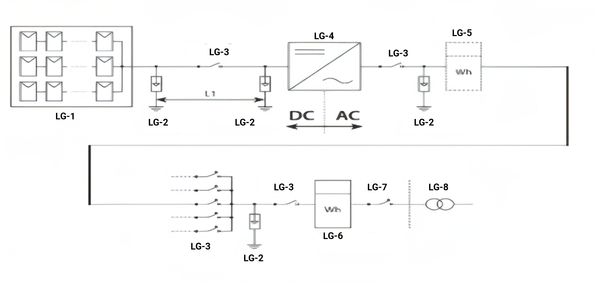
KEY
LG-1 - PV panel field
LG-2 - overvoltage protection
LG-3 - overcurrent circuit breaker
LG-4 - inverter
LG-5 - renewable energy meter
LG-6 - bidirectional energy meter
LG-7 - main switch
LG-8 - ZK
7. Final remarks
Installation of Fixtures: Lighting fixtures and socket outlets must be installed in accordance with the attached electrical installation plans, including the interior design project or direct agreements with the Investor or Supervision Inspector.
Specialized Equipment: If the building is to be equipped with alarm systems, internet access, CCTV, etc., additional supply circuits for these devices should be provided in the distribution boards. These should use independent residual current devices (RCDs) with "Type A" characteristics, which are insensitive to pulsed currents and higher frequencies, to ensure proper operation.
Compliance and Standards: All design work has been carried out in accordance with current regulations and standards, particularly PBUE, PN-IEC 60364, N SEP-E-001, and N SEP-E-002.
Commissioning: Before putting the installation into service, all necessary measurements must be performed.
Supervision: All work on electrical installations must be supervised by individuals holding the appropriate construction qualifications (building license) for managing electrical networks, installations, and power equipment.
E1 Electrical schematic of main distribution board R
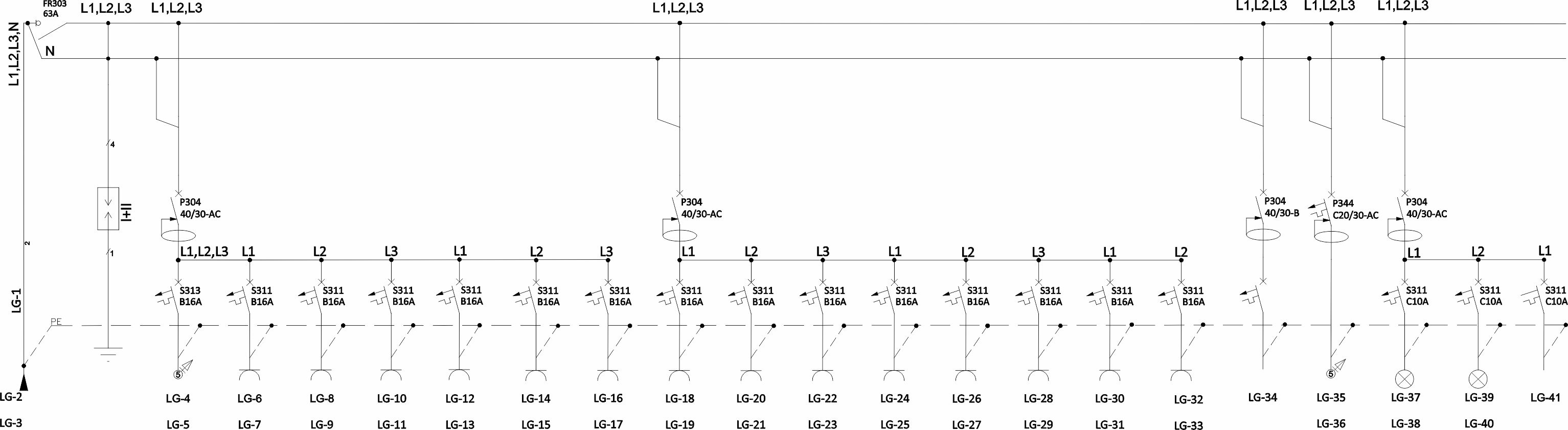
KEY
LG-1 - Power supply from main metering cabinet YKY 4x10mm
LG-2 - Room No.
LG-3 - Cable/Wire Type
LG-4 - kitchen
LG-5 - YDYp 5x2,5 cooker
LG-6 - kitchen
LG-7 - YDYp 3x2,5 dishwasher
LG-8 - kitchen utility room
LG-9 - YDYp 3x2,5 Gen. sockets range hood
LG-10 - dining room
LG-11 - YDYp 3x2,5 Gen. sockets
LG-12 - living room terrace
LG-13 - YDYp 3x2,5 Gen. sockets
LG-14 - vestibule hallway
LG-15 - YDYp 3x2,5 Gen. sockets
LG-16 - office
LG-17 - YDYp 3x2,5 Gen. sockets
LG-18 - bedroom
LG-19 - YDYp 3x2,5 Gen. sockets
LG-20 - bathroom x2 WC
LG-21 - YDYp 3x2,5 Gen. sockets
LG-22 - bedroom
LG-23 - YDYp 3x2,5 Gen. sockets
LG-24 - bedroom
LG-25 - YDYp 3x2,5 Gen. sockets
LG-26 - bedroom
LG-27 - YDYp 3x2,5 Gen. sockets
LG-28 - bedroom
LG-29 - YDYp 3x2,5 Gen. sockets
LG-30 - hallway storage
LG-31 - YDYp 3x2,5 washing machine
KEY
LG-32 - bathroom
LG-33 - YDYp 3x2,5 washing machine
LG-34 - PV system
LG-35 - storage
LG-36 - YKY 5x4 heating pump
LG-37 - ground floor
LG-38 - YDYp 3x1,5 general lighting
LG-39 - attic
LG-40 - YDYp 3x1,5general lighting
LG-41 - SPARE
NOTES
Earthing system: TN - S
Protection against direct contact (Basic protection):
- insulation of live parts
- residual current devices (RCD) I=30 mA
Protection against indirect contact (Fault protection):
- automatic disconnection of supply (ADS)
- Class II equipment
1. Distribution board R in enclosure min IP30, surface-mounted/
flush-mounted, insulated.
2. Ps = 14kW - peak power
f=50Hz
U=230/400V
Is=25A pre-meter circuit breaker
| REPETITIVE SINGLE-FAMILY RESIDENTIAL BUILDING DM-6804 |
||
| INVESTMENT TITLE / PROJECT TITLE: |
||
| ELECTRICAL | ||
| SCHEMATIC DIAGRAM OF DISTRIBUTION BOARD R | ||
| PREPARED BY / DESIGNED BY |
Tomasz Zagata, M.Sc. Eng. Licence No. PDK/0249/POOE/14 Unlimited design license in the electrical specialty |
SCALE: --- |
| ADAPTING DESIGNERS: |
DATE: 02.2021r. |
|
| E1 | ||
| COPYING AND DISTRIBUTION PROHIBITED! | ||
E2 Photovoltaic (PV) system schematic
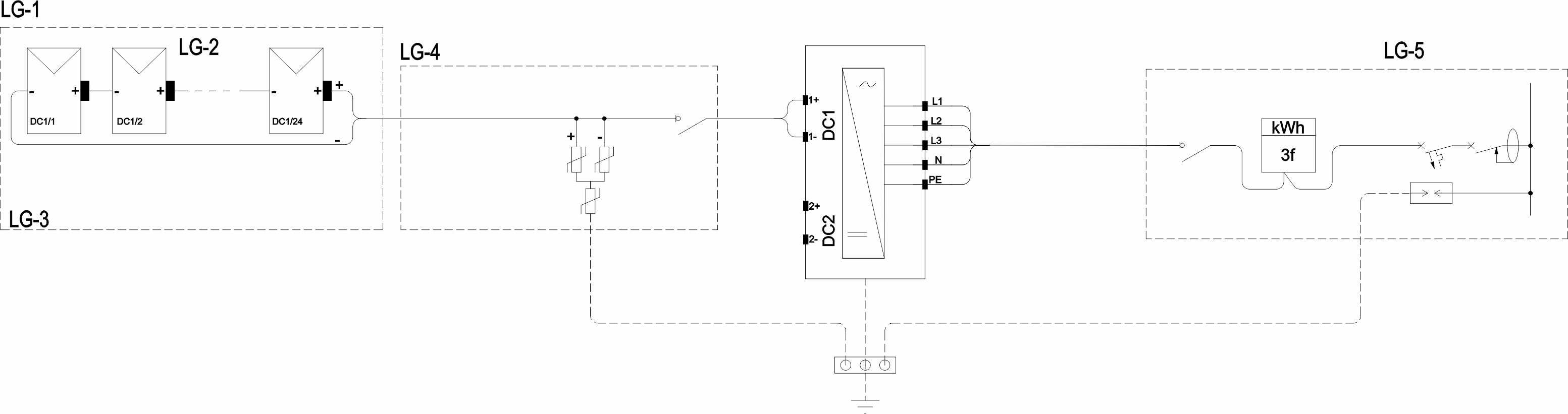
LEGEND
 |
RES metering systemwith the possibility of connectinga communication module(optional) |
 |
PV panel |
 |
power optimizer |
KEY
LG-1 - PV array
LG-2 - String 1
LG-3 - roof
LG-4 - RDC
LG-5 - Main Distribution Board R
NOTES
1. The maximum distance between the equipotential
bonding bar and the surge protective device
(SPD) is 0.5-1m.
| REPETITIVE SINGLE-FAMILY RESIDENTIAL BUILDING DM-6804 |
||
| INVESTMENT TITLE / PROJECT TITLE: |
||
| ELECTRICAL | ||
| PHOTOVOLTAIC (PV) SYSTEM SCHEMATIC | ||
| PREPARED BY / DESIGNED BY |
Tomasz Zagata, M.Sc. Eng. Licence No. PDK/0249/POOE/14 Unlimited design license in the electrical specialty |
SCALE: --- |
| ADAPTING DESIGNERS: |
DATE: 02.2021r. |
|
| E2 | ||
| COPYING AND DISTRIBUTION PROHIBITED! | ||
E3 Ground floor plan
LEGEND
 |
lighting outlet 4x1,5mm |
 |
lighting outlet 3x1,5mm |
 |
wall lighting outlet 3x1,5mm |
 |
lighting outlet 3x1,5mm for IP44 fixture |
 |
wall lighting outlet 3x1,5mm for IP44 fixture |
 |
single-pole switch |
 |
two-gang switch (chandelier switch) |
 |
two-way switch |
 |
double two-way switch |
 |
intermediate switch |
 |
400V cable outlet (1m spare cable) |
 |
230V cable outlet (1m spare cable) |
 |
single socket outlet 230V IP20 |
 |
double socket outlet 230V IP20 |
 |
double socket outlet 230V IP44 |
 |
single socket outlet 230V IP44 |
 |
R/TV/SAT socket |
 |
double RJ45 socket |
 |
RJ45 socket |
 |
proposed distribution board |
 |
equipotential bonding LgY |
 |
equipotential bonding bar (EBB) |
 |
electric cooker |
 |
cooker hood |
 |
dishwasher |
 |
washing machine |
 |
heat pump |
| NO. | ROOM NAME |
| 1 | VESTIBULE |
| 2 | HALLWAY |
| 3 | STORAGE |
| 4 | UTILITY ROOM |
| 5 | KITCHEN |
| 6 | DINING ROOM |
| 7 | LIVING ROOM |
| 8 | OFFICE |
| 9 | BEDROOM |
| 10 | BATHROOM |
| 11 | WC |
KEY
LG-1 - FeZn 30x4mm connect to ground
LG-2 - planned low-voltage cable line behind the meter
LG-3 - connection and measurement set outside the scope
of this study
LG-4 - PE electrical circuit
NOTES
1. In the kitchen and bathroom, equipotential
bonding must be installed.
2. In wet rooms and outdoors, use accessories
with a minimum rating of IP44.
3. In bathrooms and bathing areas (zones 0, 1, 2),
install only equipment intended for installation
in that specific zone
| REPETITIVE SINGLE-FAMILY RESIDENTIAL BUILDING DM-6804 |
||
| INVESTMENT TITLE / PROJECT TITLE: |
||
| ELECTRICAL | ||
| GROUND FLOOR PLAN | ||
| PREPARED BY / DESIGNED BY |
Tomasz Zagata, M.Sc. Eng. Licence No. PDK/0249/POOE/14 Unlimited design license in the electrical specialty |
SCALE: 1:100 |
| ADAPTING DESIGNERS: |
DATE: 02.2021r. |
|
| E3 | ||
| COPYING AND DISTRIBUTION PROHIBITED! | ||
E4 Attic plan
LEGEND
|
lighting outlet 4x1,5mm |
|
lighting outlet 3x1,5mm |
|
wall lighting outlet 3x1,5mm |
|
lighting outlet 3x1,5mm for IP44 fixture |
|
wall lighting outlet 3x1,5mm for IP44 fixture |
|
single-pole switch |
|
two-gang switch (chandelier switch) |
|
two-way switch |
|
double two-way switch |
|
intermediate switch |
|
400V cable outlet (1m spare cable) |
|
230V cable outlet (1m spare cable) |
|
single socket outlet 230V IP20 |
|
double socket outlet 230V IP20 |
|
double socket outlet 230V IP44 |
|
single socket outlet 230V IP44 |
|
R/TV/SAT socket |
|
double RJ45 socket |
|
RJ45 socket |
|
proposed distribution board |
|
equipotential bonding LgY |
|
equipotential bonding bar (EBB) |
|
electric cooker |
|
cooker hood |
|
dishwasher |
|
washing machine |
|
heat pump |
| NO. | ROOM NAME |
| 12 | HALLWAY |
| 13 | BEDROOM |
| 14 | BEDROOM |
| 15 | STORAGE |
| 16 | BEDROOM |
| 17 | BEDROOM |
| 18 | BATHROOM |
KEY
LG-1 - PE electrical circuit
NOTES
1. In the kitchen and bathroom, equipotential
bonding must be installed.
2. In wet rooms and outdoors, use accessories
with a minimum rating of IP44.
3. In bathrooms and bathing areas (zones 0, 1, 2),
install only equipment intended for installation
in that specific zone
| REPETITIVE SINGLE-FAMILY RESIDENTIAL BUILDING DM-6804 |
||
| INVESTMENT TITLE / PROJECT TITLE: |
||
| ELECTRICAL | ||
| ATTIC PLAN | ||
| PREPARED BY / DESIGNED BY |
Tomasz Zagata, M.Sc. Eng. Licence No. PDK/0249/POOE/14 Unlimited design license in the electrical specialty |
SCALE: 1:100 |
| ADAPTING DESIGNERS: |
DATE: 02.2021r. |
|
| E4 | ||
| COPYING AND DISTRIBUTION PROHIBITED! | ||
E5 Roof plan
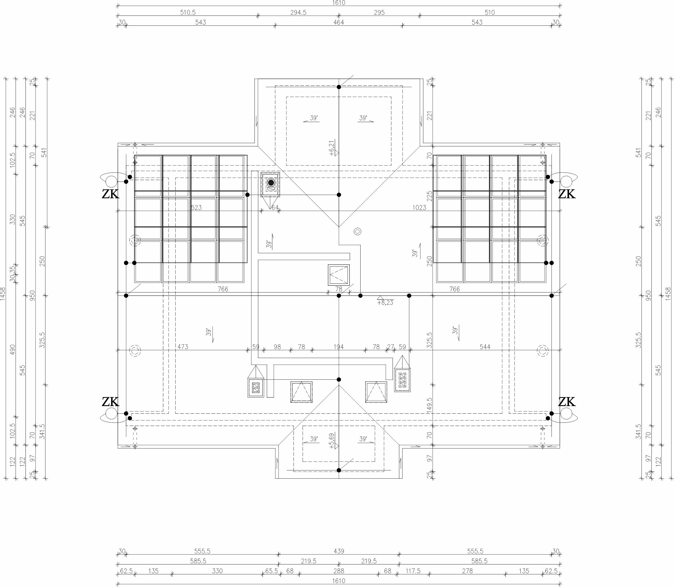
LEGEND
 |
test joint |
 |
vertical air terminal |
 |
PV panel |
NOTES
1. Install four down conductors in PVC conduits within the building elevation.
2. Make disconnectable test joints using ZK test terminals with an earthing
conductor.
3. Place test terminals in flush-mounted test boxes.
4. Fix horizontal air terminals on the roof using holders spaced every 1m.
5. Protect roof installations using air terminal masts and vertical conductors
of a height adapted to Class IV protection.
6.Maintain the required separation distance from windows, entrance doors,
and roof-mounted equipment protected by the system.
7. To protect against touch and step voltages, ensure the ground surface layer
within a 3m radius of down conductors has a resistivity of no less than 5k$\Omega$
by laying 5cm of asphalt or a 15cm layer of gravel.
8. Use 30x4mm galvanized steel tape (FeZn) laid in the lower layer of the foundation
reinforcement as a foundation earth electrode. The earthing resistance must not exceed
10W. Lead the earth electrode connection points out from the foundation using 30x4mm
stainless steel tape to the equipotential bonding bar and down conductors. In case of
waterproof insulation, place the earth electrode in the lean concrete layer.
| REPETITIVE SINGLE-FAMILY RESIDENTIAL BUILDING DM-6804 |
||
| INVESTMENT TITLE / PROJECT TITLE: |
||
| ELECTRICAL | ||
| ROOF PLAN | ||
| PREPARED BY / DESIGNED BY |
Tomasz Zagata, M.Sc. Eng. Licence No. PDK/0249/POOE/14 Unlimited design license in the electrical specialty |
SCALE: 1:100 |
| ADAPTING DESIGNERS: |
DATE: 02.2021r. |
|
| E5 | ||
| COPYING AND DISTRIBUTION PROHIBITED! | ||